Width probe – HEIDENHAIN IK 5494-2D User Manual
Page 119
97
4
Probes
Width Probe
The Width probe uses edge detection scanned in opposing directions to return two points on op-
posite sides of a line each time it is fired. Many points on both sides of the line are acquired and
processed by the width algorithm to find the average line width. The default of 50 points can be
changed by supervisors, distributors and OEMs in the Probe Library.
The Width probe is used to measure line widths that are returned as distances in the Features template.
Select the probe from the Probe menu,
the live video window on-screen
menu or the VED toolbar. Move the
probe, change its size or change its
orientation as described earlier in this
chapter.
To measure line width, select and po-
sition the Width probe over the line
and then click the center mouse but-
ton to fire the Probe.
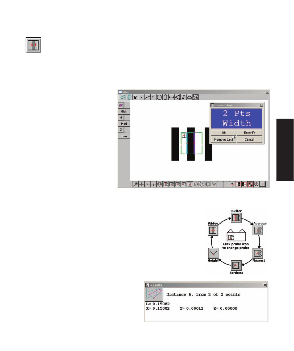
The Width probe can be obtained from a collection of six probes by clicking
on the probe icon. Repeatedly clicking the probe icon cycles through the six
probes shown in this diagram.
Measurement results are sent to the Features template and the Results win-
dow. Width measurement results include:
• The feature type and feature number
• The number of points acquired and the
number of points used to calculate
feature data
• The length (width) across the line
• The geometric center location of the feature
The width of a line is returned as two opposing points
Video Probe Descriptions