Circle center i, j, k -16 – HEIDENHAIN TNC 360 ISO Programming User Manual
Page 99
5-16
5
Programming Tool Movements
TNC 360
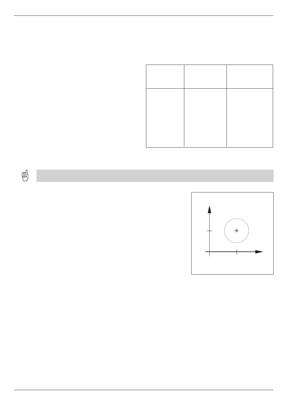
Fig. 5.21:
Circle center I, J
Fig. 5.20:
Defining the spindle axis also defines the main plane and the
circle center designations
5.4
Path Contours - Cartesian Coordinates
Main plane
XY G17
ZX G18
YZ G19
Spindle axis
Z
Y
X
Circle center
I J
K I
J K
Y
X
J
I
Radius compensation in circular paths
You cannot begin radius compensation in a circle block. It must be
activated beforehand in a line block.
Circles in the main planes
When you program a circle, the TNC assigns it to
one of the main planes. This plane is automatically
defined when you set the spindle axis during tool
call (T).
You can program circles that do not lie parallel to a main plane by using Q parameters (see Chapter 7).
Circle center I, J, K
If you program an arc using the functions G02/G03/G05, you must first
define the circle center by:
• entering the Cartesian coordinates of the circle center
• using the circle center defined in an earlier block
• capturing the actual position
You can define the last programmed position as circle center/pole by
programming G29.
Duration of a circle center definition
A circle center definition remains effective until a new circle center is
defined.