5 machine-specific user parameters -4, 6 selecting position display types -4, 5 machine-specific user parameters – HEIDENHAIN TNC 360 ISO Programming User Manual
Page 198: 6 selecting position display types
TNC 360
10-4
10
MOD Functions
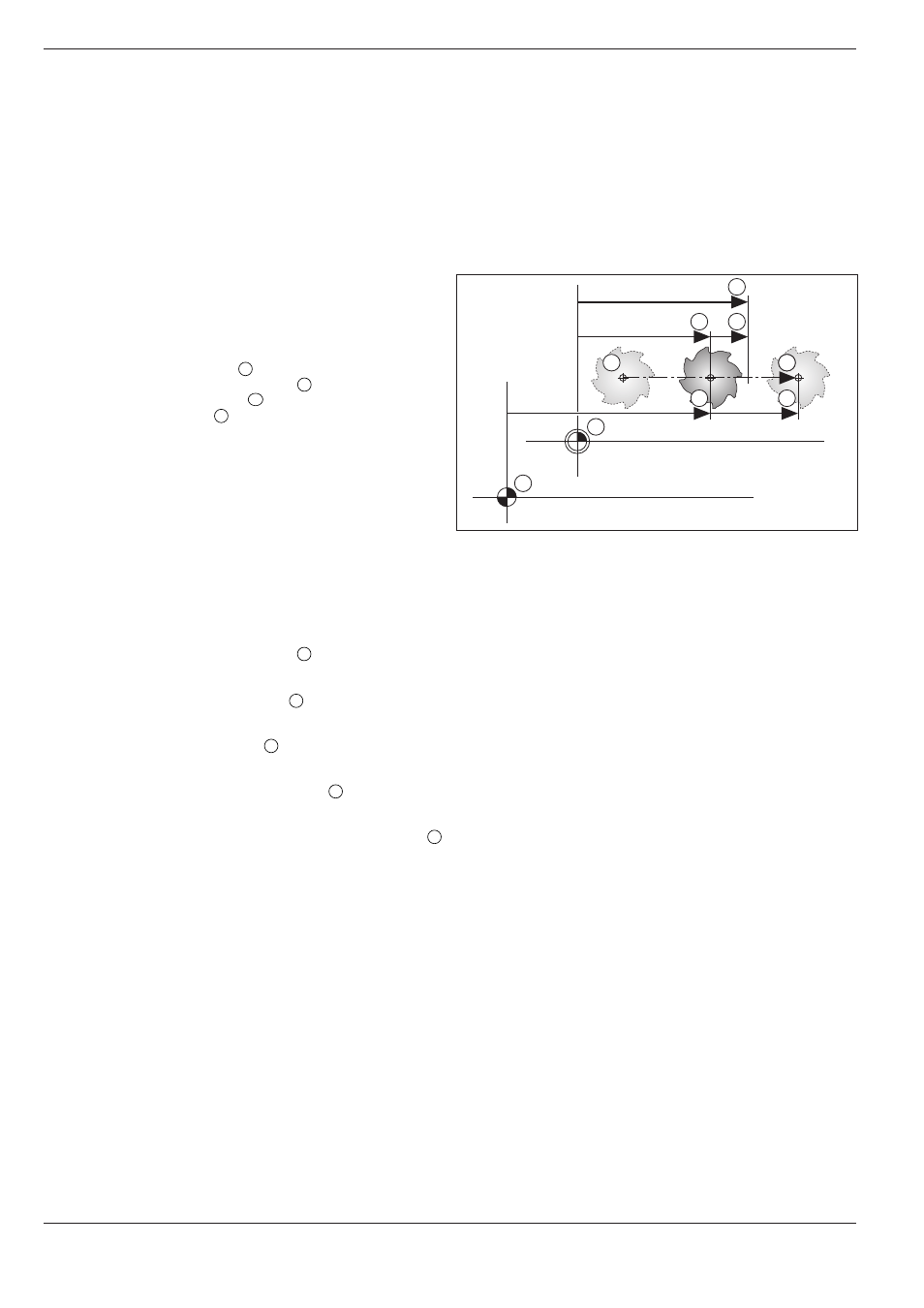
Fig. 10.1:
Characteristic positions on the workpiece and scale
5
4
2
3
1
Z
Z
A
W
M
10.5 Machine-Specific User Parameters
The machine tool builder can assign functions to up to 16 USER PARAME-
TERS. For more detailed information, refer to the operating manual for the
machine tool.
10.6 Selecting Position Display Types
The positions indicated in Fig. 10.1 are:
• Starting position
A
• Target position of the tool
Z
• Workpiece datum
W
• Scale datum
M
The TNC position display can show the
following coordinates:
• Nominal position (the value presently
commanded by the TNC)
1
...................................................... NOML.
• Actual position (the position at which the
tool is presently located)
2
........................................................ ACTL.
• Servo lag (difference between the nominal
and actual positions)
3
.............................................................. LAG
• Reference position (the actual position as
referenced to the scale datum)
4
.............................................. REF
• Distance remaining to the programmed position
(difference between actual and target position)
5
.................... DIST.
Select the desired information with the ENT key. It is then displayed
directly in the status field.