Α? α – HEIDENHAIN TNC 360 ISO Programming User Manual
Page 146
TNC 360
7-12
7
Programming with Q Parameters
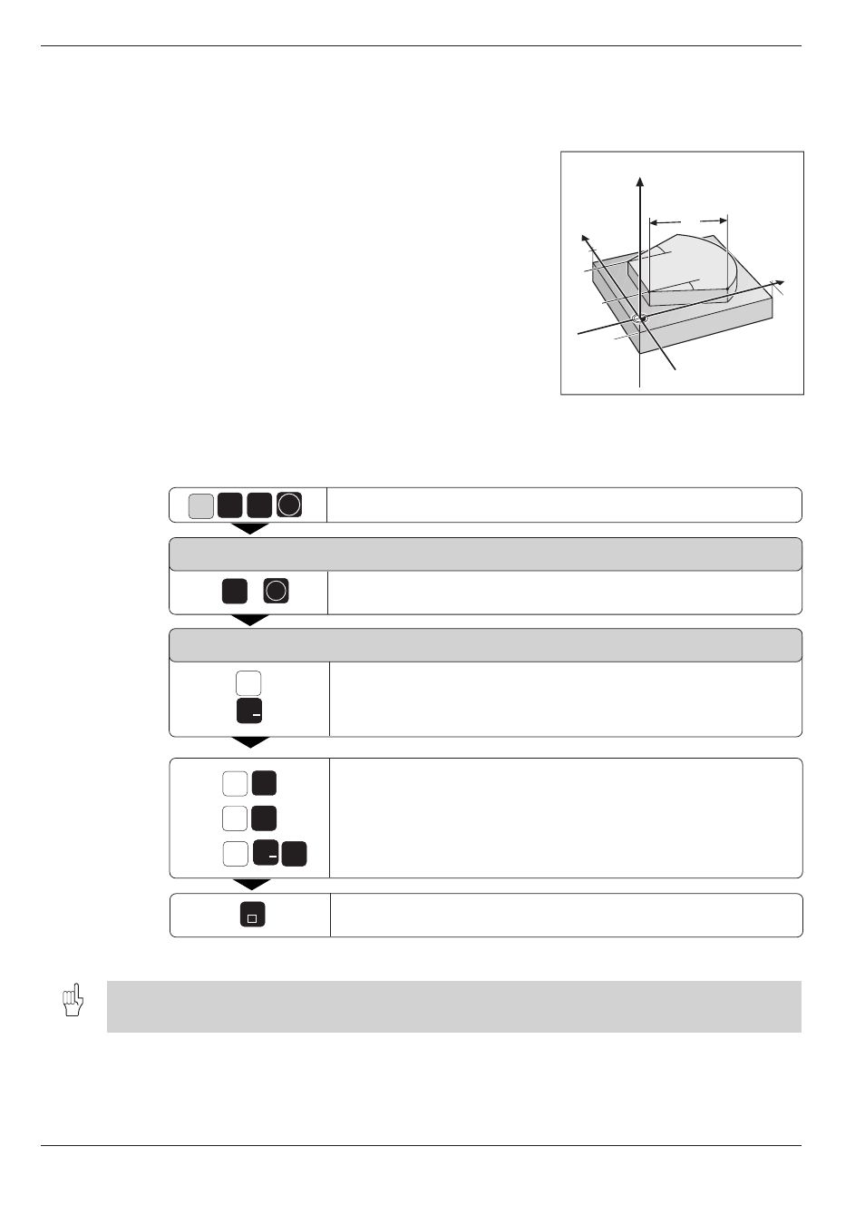
Fig. 7.4:
Workpiece dimensions to be
measured
e.g.
0
e.g.
e.g.
Z
5
5
5
e.g.
ENT
100
–10
100
α
?
α
?
Y
X
Z
L?
ENT
5
5
e.g.
X
Y
G
+/
X
e.g.
+/
END
7.7 Measuring with the 3D Touch Probe During Program Run
The 3D touch probe can measure positions on a workpiece during pro-
gram run.
Applications:
• Measuring differences in the height of cast surfaces
• Checking tolerances during machining
Enter G55 to activate the touch probe.
The touch probe is automatically pre-positioned (with rapid traverse from
MP6150) and probes the specified position (with feed rate from MP6120).
The coordinate measured for the probe point is stored in a Q parameter.
The TNC interrupts the probing process if the probe is not deflected within
a certain range (range selected with MP6130).
To program the use of a touch probe:
Select the touch probe function.
PARAMETER NUMBER FOR RESULT ?
Enter the number of the Q parameter to which the coordinate is to be
assigned, for example Q5.
PROBING AXIS/PROBING DIRECTION?
Enter the probing axis for the coordinate, for example X.
Select and confirm the probing direction.
Enter all coordinates of the pre-positioning point values,
for example X = 5 mm, Y = 0, Z = –5 mm.
Conclude input.
Resulting NC block: N150 G55 P01 05 P02 X- X+5 Y+0 Z-5 *
Pre-position the touch probe manually such that it will not collide with the workpiece when it moves toward the
programmed position.