Pocket milling g75/g76 -11 – HEIDENHAIN TNC 360 ISO Programming User Manual
Page 164
8-11
8
Cycles
TNC 360
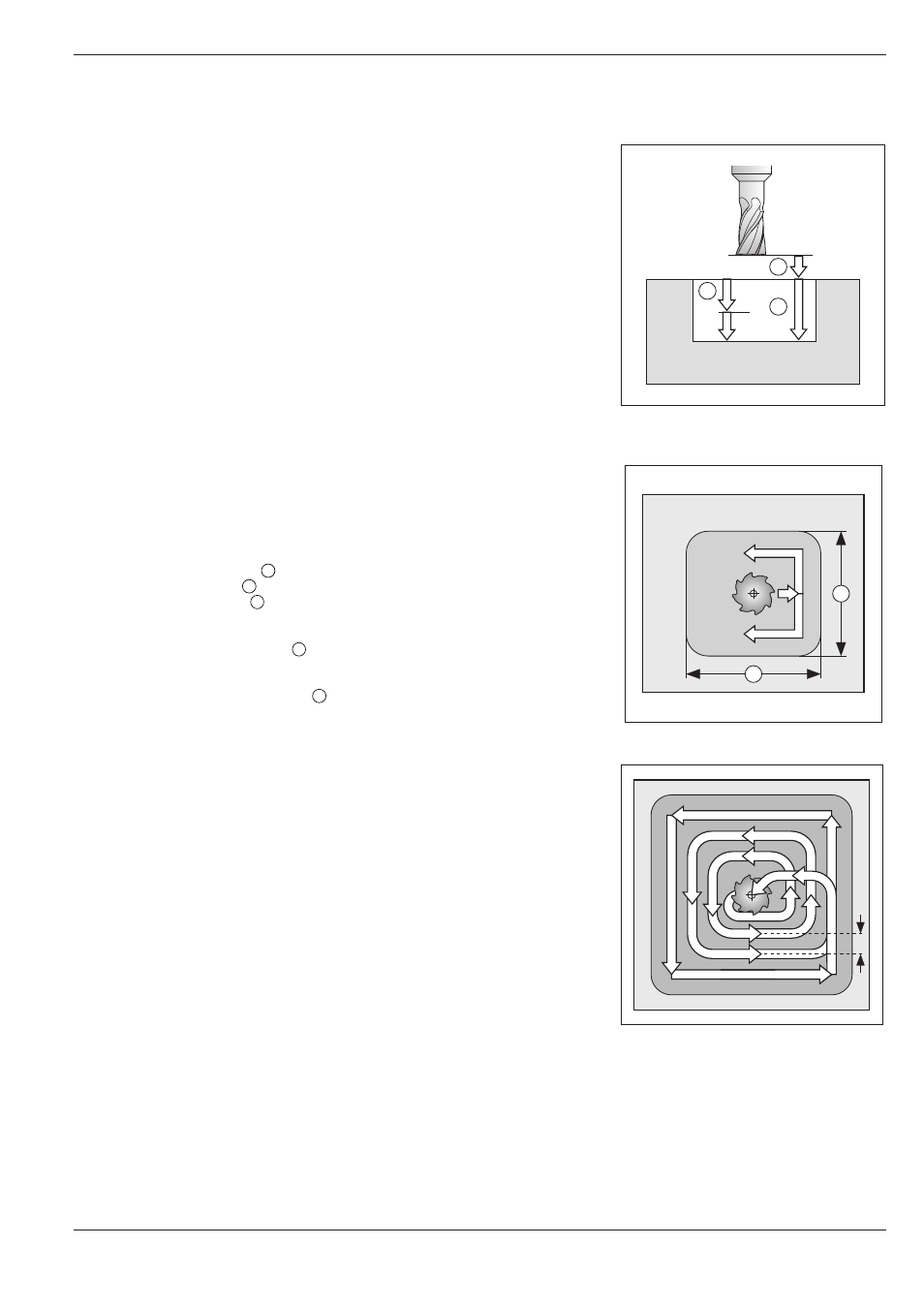
Fig. 8.8:
Side lengths of the pocket
Fig. 8.7:
Infeeds and distances for the
POCKET MILLING cycle
8.2
Simple Fixed Cycles
A
B
C
Fig. 8.9:
Tool path for roughing out
k
E
D
G76
G75
F
POCKET MILLING G75/G76
Process
The rectangular pocket milling cycle is a roughing cycle, in which
• the tool penetrates the workpiece at the starting position (pocket
center)
• the tool subsequently follows the programmed path at the specified
feed rate (see Fig. 8.9).
The cutter begins milling in the positive axis direction of the longer side.
With square pockets, the cutter begins in the positive Y direction. At the
end of the cycle, the tool returns to the starting position.
Requirements / Limitations
This cycle requires a center-cut end mill (ISO 1641) or a separate pilot
drilling operation at the pocket center. The pocket sides are parallel to the
axes of the coordinate system.
Direction of rotation for roughing out
Clockwise direction of rotation: G75
Counterclockwise direction of rotation: G76
Input data
• Setup clearance
A
• Milling depth
B
• Pecking depth
C
• FEED RATE FOR PECKING:
Traversing speed of the tool during penetration.
• FIRST SIDE LENGTH
D
:
Length of the pocket, parallel to the first main axis of the working
plane.
• SECOND SIDE LENGTH
E
:
Width of the pocket
The signs of the side lengths are always positive.
• FEED RATE:
Traversing speed of the tool in the working plane.
Calculations
Stepover factor k:
k = K x R
K:
Overlap factor (preset by the machine tool builder)
R:
Cutter radius
Rounding radius
The pocket corners are rounded with the cutter radius.