Helical interpolation -33, Yx z, Helical interpolation – HEIDENHAIN TNC 360 ISO Programming User Manual
Page 116
5-33
TNC 360
5
Programming Tool Movements
Helical interpolation
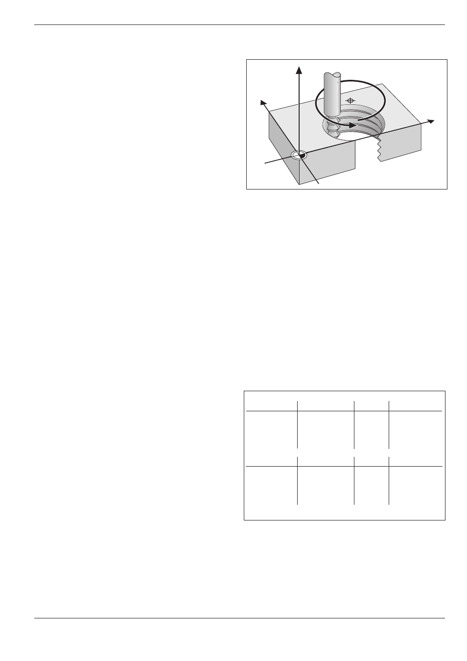
A helix is the combination of a circular movement in
a main plane and a linear movement perpendicular
to the plane.
A helix is programmed only in polar coordinates.
Applications
You can use helical interpolation with form cutters
to machine:
• Large-diameter internal and external threads
• Lubrication grooves
Input
• Total incremental angle of tool traverse on the helix
• Total height of the helix
Input angle
Calculate the incremental polar coordinate angle G91 H as follows:
H = n
.
360°.
n = number of revolutions of the helical path
For G91 H you can enter any value from –5400° to +5400° (n = 15).
Input height
Enter the helix height h in the tool axis. The height is calculated as:
h = n x P,
n = number of thread revolutions
P = thread pitch
Radius compensation
Enter the radius compensation for the helix
according to the table at right.
Fig. 5.38: Helix: a combination of circular and linear paths
5.5
Path Contours - Polar Coordinates
Fig. 5.39:
The shape of the helix determines the direction of rotation
and the radius compensation
External thread
Right-hand
Left-hand
Right-hand
Left-hand
Work direction
Z+
Z+
Z–
Z–
Internal thread
Right-hand
Left-hand
Right-hand
Left-hand
Work direction
Z+
Z+
Z–
Z–
Rotation
G13
G12
G12
G13
Radius comp.
G41
G42
G42
G41
Rotation
G13
G12
G12
G13
Radius comp.
G42
G41
G41
G42
Y
X
Z
I, J