Overview of path functions -9 – HEIDENHAIN TNC 360 ISO Programming User Manual
Page 92

5-9
TNC 360
5
Programming Tool Movements
Overview of path functions
5.3
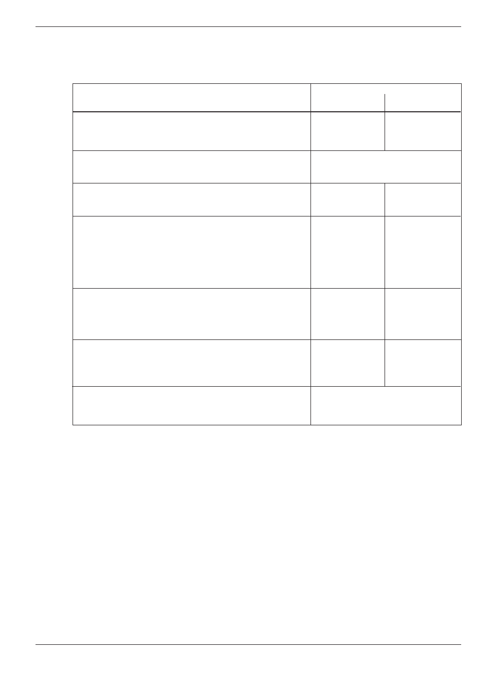
Path Functions
Input
Function
in Cartesian
in polar
coordinates
coordinates
Straight line at rapid traverse.
G00
G10
Straight line with a programmed feed rate.
G01
G11
Chamfer with chamfer length R.
G24
A chamfer is inserted between two intersecting straight lines.
Circle center – at the same time a reference for polar coordinates.
I, J, K
I,J,K do not generate a movement.
Circular movement in the clockwise direction (CW).
G02
G12
Circular movement in the counterclockwise direction (CCW).
G03
G13
A circular path can be programmed by entering:
• Circle center I, J, K and end point, or
• Circle radius and end point.
Circular path with no direction of rotation defined.
G05
G15
The circular path is programmed by entering circle center and end
point. The direction of rotation is taken from the last programmed
circular movement (G02/G12 or G03/G13).
Circular movement with tangential connection.
G06
G16
A circular arc is connected tangentially with the previously pro-
grammed contour element. The end point of the circular arc is
entered in the part program.
Corner rounding with radius R.
G25
A circular arc is inserted to connect tangentially both with the pre-
ceding and the subsequent contour elements.
