Additional axes -8 polar coordinates -8 – HEIDENHAIN TNC 360 ISO Programming User Manual
Page 25
TNC 360
1-8
1
Introduction
Additional axes
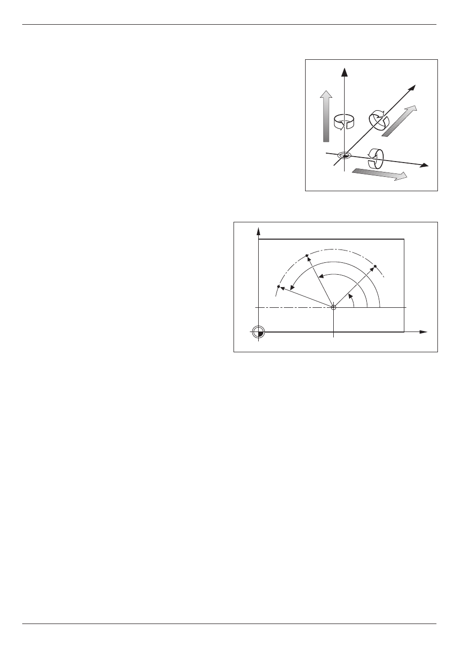
The TNC can control machines that have more than three axes. U, V and
W are secondary linear axes parallel to the main axes X, Y and Z, respec-
tively (see illustration). Rotary axes are also possible. They are designated
as axes A, B and C.
Polar coordinates
The Cartesian coordinate system is especially
useful for parts whose dimensions are mutually
perpendicular. But when workpieces contain
circular arcs, or when dimensions are given in
degrees, it is often easier to use polar coordinates.
In contrast to Cartesian coordinates, which are
three-dimensional, polar coordinates can only
describe positions in a plane.
The datum for polar coordinates is the pole I, J, K.
To describe a position in polar coordinates, think of
a scale whose zero point is rigidly connected to the
pole but which can be freely rotated in a plane
around the pole.
Positions in this plane are defined by:
• Polar Radius R: The distance from the pole I, J
to the defined position.
• Polar Angle H: The angle between the refer-
ence axis and the scale.
Fig. 1.10:
Arrangement and designation of
the auxiliary axes
Fig. 1.11:
Positions on an arc with polar coordinates
1.2
Fundamentals of NC
Y
B+
V+
X
Z
C+
A+
W+
U+
X
Y
J = 10
0
°
I = 30
H
1
H
2
H
3
R
R
R