The operating panel -3 the screen -3, The operating panel, The screen – HEIDENHAIN TNC 360 ISO Programming User Manual
Page 20: Numerical entries • axis selection operating modes
TNC 360
1-3
1
Introduction
.
0
1
2
3
4
5
6
7
8
9
+/
Z
Y
X
CE
C
CC
CT
CR
IV
RND
PGM
CALL
PGM
NR
CL
PGM
L
MOD
BLK
FORM
MAGN
START
Q
DEF
P
MOD
END
Q
0
50
100
150
0
50
100
150
S %
F %
GRAPHICS
R
+
R
R-
L
TOOL
CALL
TOOL
DEF
NO
ENT
CYCL
CALL
CYCL
DEF
STOP
LBL
CALL
LBL
SET
GOTO
EXT
TOUCH
PROBE
DEL
ENT
HEIDENHAIN
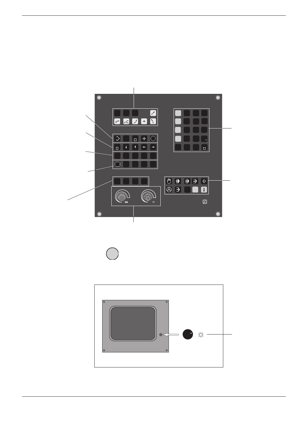
The Operating Panel
The keys on the TNC operating panel are grouped according to their
functions:
• Program selection
• Address letters
1.1
The TNC 360
• External data transfer
• Probing functions
• Editing functions
• Jump instruction GOTO
• Arrow keys
• Address letters
• NO ENT key
• Tool-related address letters
Override controls
for spindle speed
and feed rate
The functions of the individual keys are de-
scribed on the inside front cover. An overview
of the address letters used for ISO program-
ming is provided in Chapter 11.
Graphic operating
modes
The machine operating buttons, such as for NC start, are described in the manual for your machine tool.
In this manual they are shown in gray.
The Screen
Brightness control
(BE 212 only)
Header
The header of the screen shows the selected operating mode. Dialog
questions and TNC messages also appear there.
I
• Numerical entries
• Axis selection
Operating modes