Switcher input tables – Grass Valley Trinix v.2.4.1 User Manual
Page 190
Protected Path Configuration
190
Planning and Installation Manual
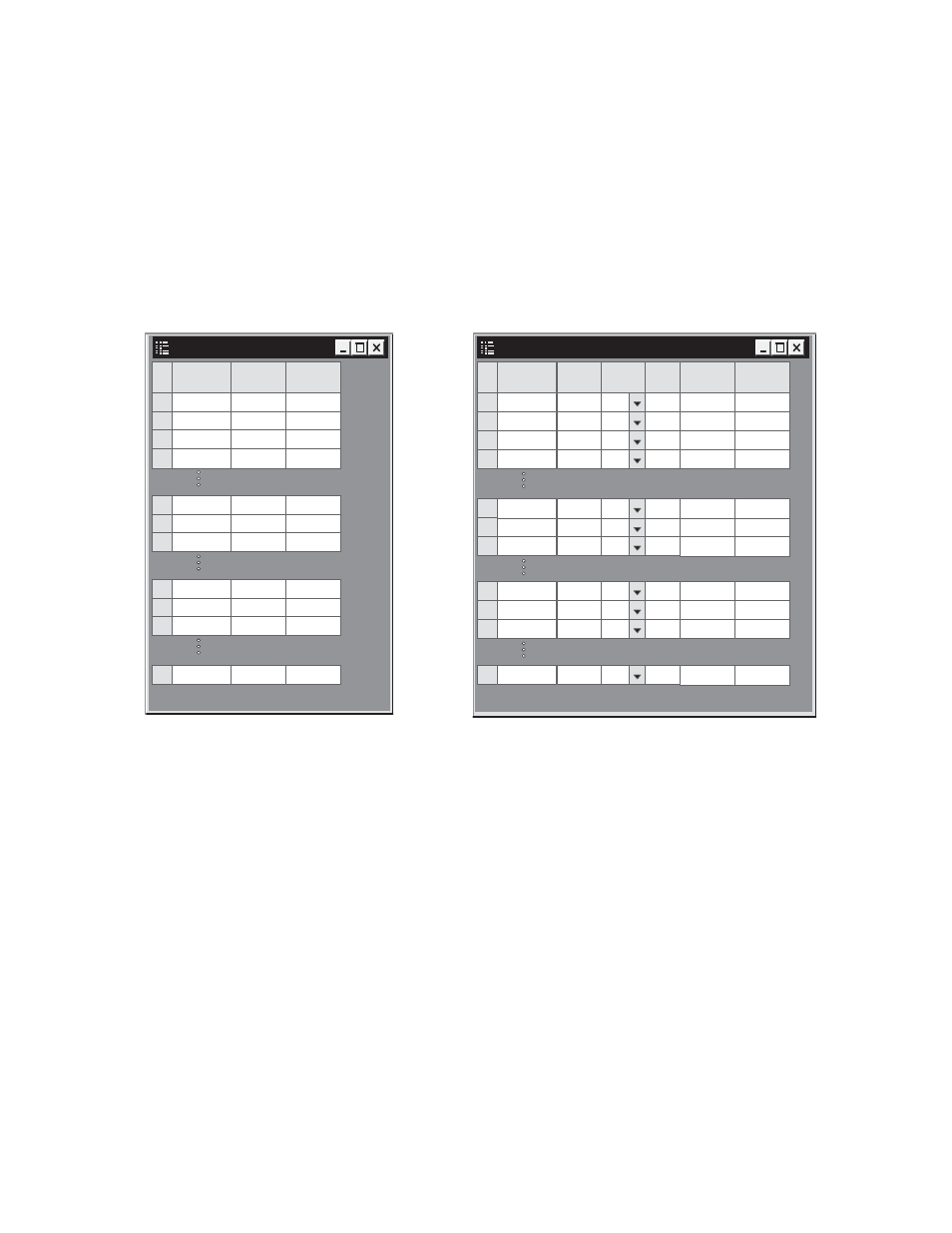
Switcher Input Tables
With two logical levels defined on the Switcher Description table, the
Switcher Input and Switcher Output tables will automatically show a
column for each level.
In order to perform two-level switching, Switcher Input tables and
Switcher Output tables are used to describe the primary and secondary
paths.
Figure 113.
In this example, the Switcher Input table for the Primary level would
list 480 inputs: 001 through 256 and 289 through 512. The Secondary
level would list 32 inputs: 257 through 288.
The same logic would apply to Switcher Output tables.
In this configuration, selecting “XMIT” as an output and “MCON-
TROL” as an input will cause two switches to be made.
Finally, CP Input and CP Output Set tables would be used to tie Cate-
gory/Number selections to the logical names of the desired inputs and
outputs on both levels.
For more information about logical level mapping, refer to the Jupiter
Installation and Operating manual.
Switcher Input - MAINROUT
1
Logical Input
Name
2
001
002
MCONTROL
PRIMARY
257
258
3
4
003
VT02
VT01
259
004
260
32
032
288
SECONDAR
AUX4
33
033
AUX5
34
034
AUX5
480
512
BARS
VT03
256
256
CH25
257
289
CH26
258
290
CH27
Switcher Output - MAINROUT
1
Logical Ouput
Name
2
001
002
XMIT
PRIMARY
257
258
3
003
VT02
VT01
259
SECONDAR
S-T
-
-
-
Security
4
004
VT03
260
-
-
-
-
-
Pass
word
32
032
288
AUX4
33
033
AUX5
34
034
AUX5
-
-
-
256
256
SAT13
257
289
SAT14
258
290
SAT15
480
512
MAT MON