Setting the output monitor address – Grass Valley Trinix v.2.4.1 User Manual
Page 141
Output Monitoring
Planning and Installation Manual
141
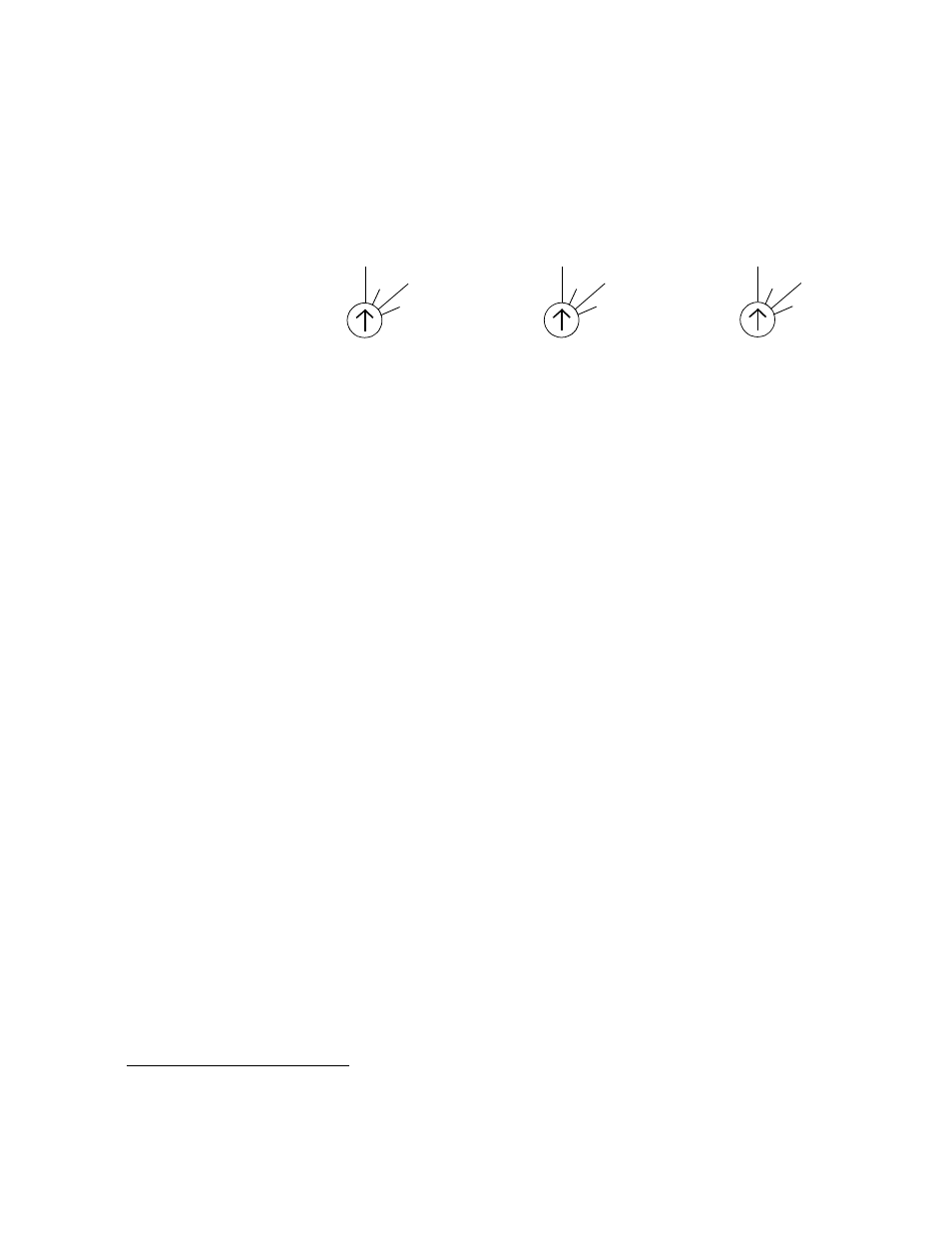
Setting the Output Monitor Address
Figure 76. Output Monitor Address Switches
Note
On all the rotary switches, use the triangular arrowhead for pointing (not
the screwdriver slot).
Note
Some units in the field may have incorrect labels on these switches. The
labels shown in
are correct.
The “Monitor” rotary switch on the back panel is used to set the control
address for the available monitor outputs. For example, with a 128 x 128
switcher equipped with redundant NR-33000 boards, the quality
control monitor could be connected to output monitor connector “1”
and the monitor switch set to “128”; the control system would then
select Output 129* for monitoring purposes. See
.
If the router has been output-expanded (as described on
), then
each Monitor switch would be set to the highest output number for the
system. For example, if a DV-33128 has been output-expanded to 128 x
256, the Monitor switch would be set to “256” on both chassis.
The second BNC connector of each pair provides an inverted output
signal.
128
256
384
512
DV-33128 CHASSIS
256
512
768
1024
DV-33256 CHASSIS
512
1024 1536
2048
DV-33512 CHASSIS
MONITOR
MONITOR
MONITOR
*For Jupiter-controlled (0-based) systems, subtract one (1) from these numbers.