Grass Valley Trinix v.2.4.1 User Manual
Page 168
Broadlinx
168
Planning and Installation Manual
Checking Hardware Status
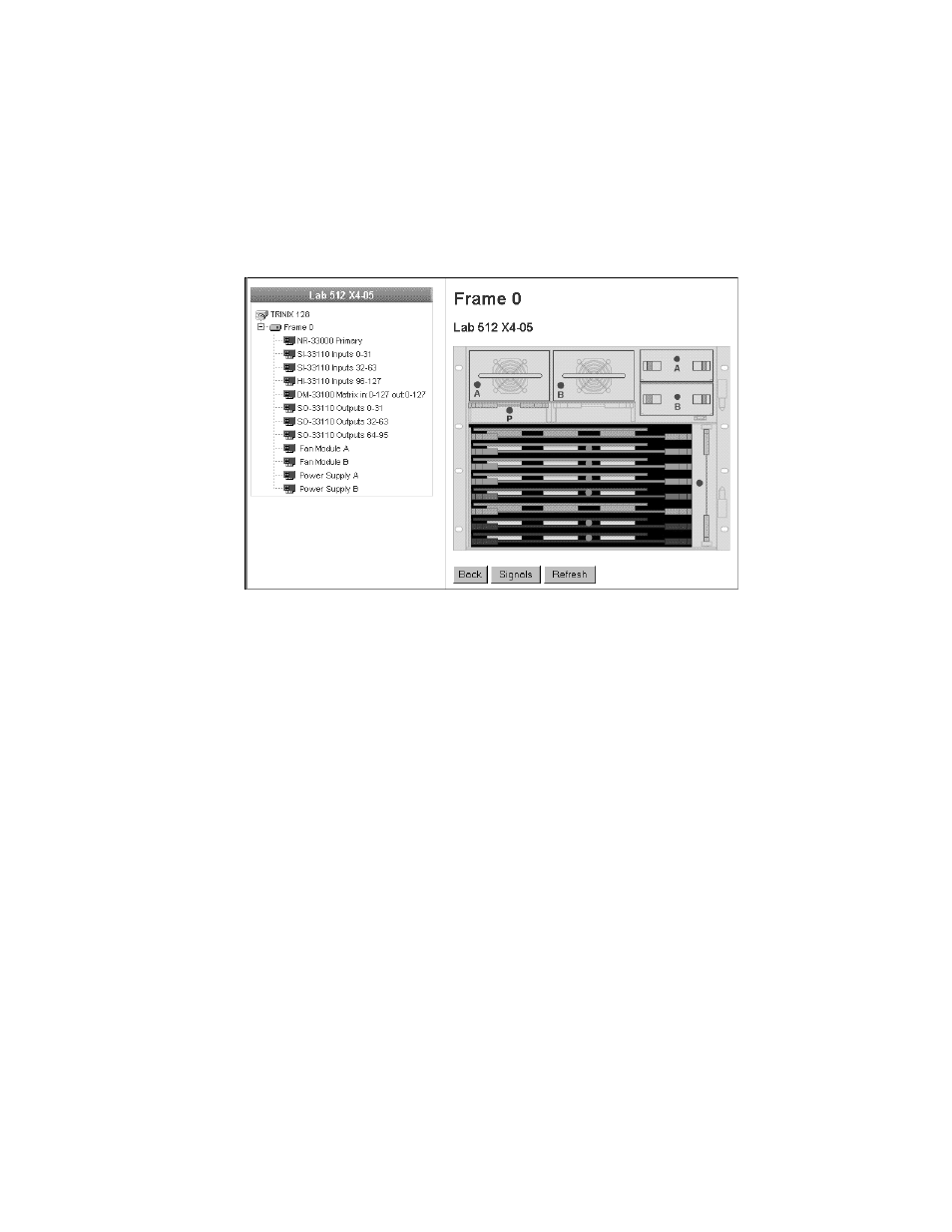
1.
Connect to the router following the procedure just described.
2.
Click on the graphic of the router front panel. A line drawing of the
Trinix chassis will appear (similar to
).
Figure 96.
In this example, all modules and boards show a green dot meaning
that operation is normal.
3.
Click on a module or board to check its condition. See
You can click either on the name in the list or on the graphic.
For DV-33512 routers, the SR-33500 Sync Reference board and the
RP-33500 Rear Panel must be selected from the list (because these
boards on located on the rear panel).
See also other documents in the category Grass Valley Equipment:
- LDK 5302 (24 pages)
- SFP Optical Converters (18 pages)
- 2000GEN (22 pages)
- 2011RDA (28 pages)
- 2010RDA-16 (28 pages)
- 2000NET v3.2.2 (72 pages)
- 2000NET v3.1 (68 pages)
- 2020DAC D-To-A (30 pages)
- 2000NET v4.0.0 (92 pages)
- 2020ADC A-To-D (32 pages)
- 2030RDA (36 pages)
- 2031RDA-SM (38 pages)
- 2041EDA (20 pages)
- 2040RDA (24 pages)
- 2041RDA (24 pages)
- 2042EDA (26 pages)
- 2090MDC (30 pages)
- 2040RDA-FR (52 pages)
- LDK 4021 (22 pages)
- 3DX-3901 (38 pages)
- LDK 4420 (82 pages)
- LDK 5307 (40 pages)
- Maestro Master Control Installation v.1.5.1 (455 pages)
- Maestro Master Control Installation v.1.5.1 (428 pages)
- 7600REF Installation (16 pages)
- 7600REF (84 pages)
- 8900FSS (18 pages)
- 8900GEN-SM (50 pages)
- 8900NET v.4.3.0 (108 pages)
- Safety Summary (17 pages)
- 8900NET v.4.0.0 (94 pages)
- 8906 (34 pages)
- 8911 (16 pages)
- 8900NET v.3.2.2 (78 pages)
- 8914 (18 pages)
- 8912RDA-D (20 pages)
- 8916 (26 pages)
- 8910ADA-SR (58 pages)
- 8920ADC v.2.0 (28 pages)
- 8920ADC v.2.0.1A (40 pages)
- 8920DAC (28 pages)
- 8920DMX (30 pages)
- 8920ADT (36 pages)
- 8920MUX (50 pages)
- 8921ADT (58 pages)