Grass Valley Trinix v.2.4.1 User Manual
Page 151
Jupiter Control
Planning and Installation Manual
151
2.
Set the Trinix “INT XPT CNTL” rear-panel DIP switch to Off (switch
open). See
.
Figure 83.
This will cause the Broadlinx board to release control of the Trinix
internal crosspoint bus. Switch commands arriving at the cross-
point bus connector on the rear of the chassis will be executed.
3.
Set Level switches:
Two back-panel rotary switches are used to set the level address of
the router.
For Jupiter control “Super” crosspoint bus settings are used: the
left-hand switch is turned to the appropriate most significant bit on
the “Super” side of the switch. The least significant bit is set on the
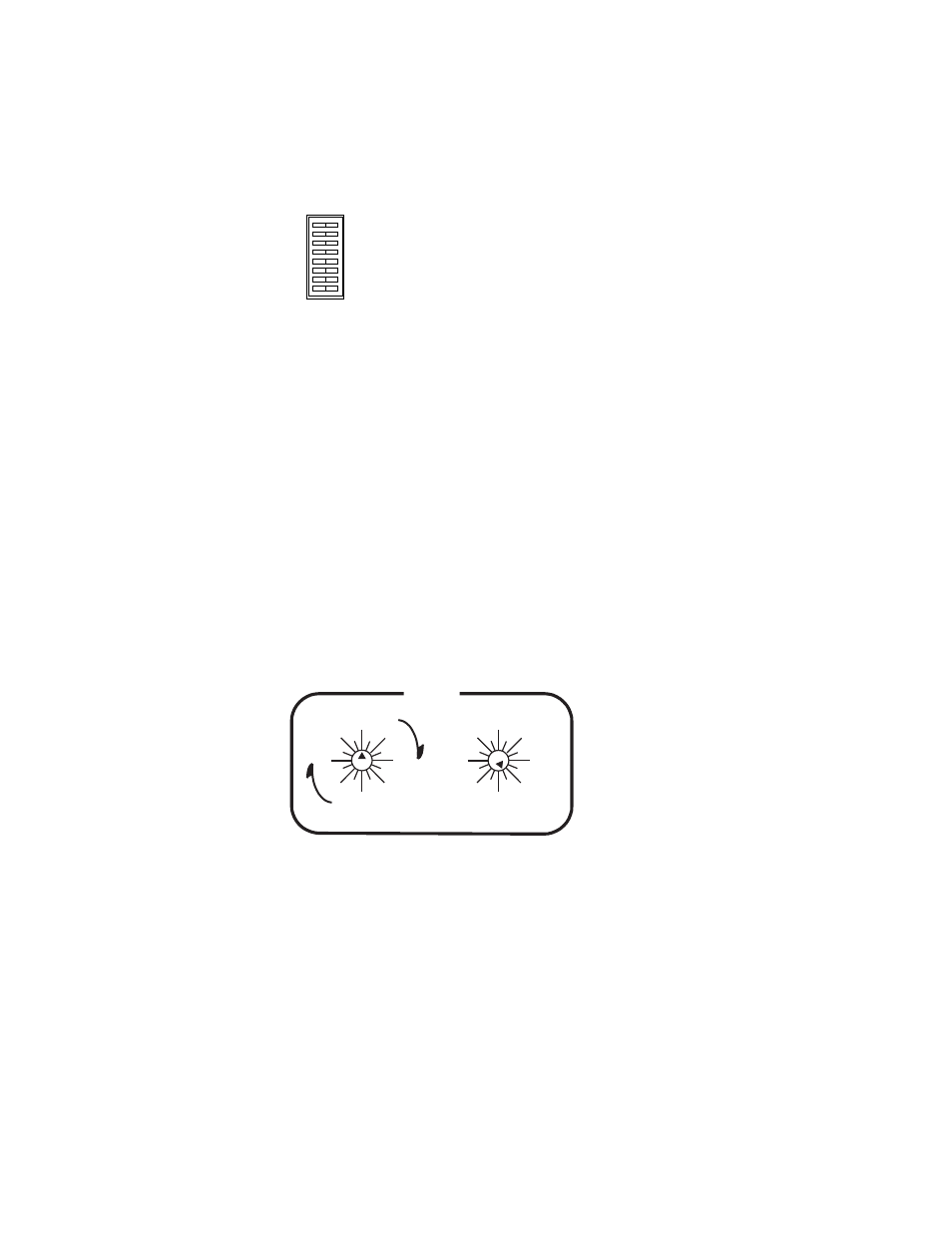
right switch. For example, to set the switcher level at “7” (the
factory default for serial digital video) the left switch would be set
at “Super 0” (straight up) and the right switch set to “7.” See
.
Figure 84.
Note
On all the rotary switches, use the triangular arrowhead for pointing (not
the screwdriver slot).
4.
For synchronous switching on all outputs, the same sync signal
must be sent to the Jupiter and to the Trinix.
5.
Connect the LAN and Com Bus as required.
In most cases, the Trinix should be connected to the facility LAN to
allow system monitoring via the Broadlinx application. Com Bus
connections will be needed for Broadlinx monitoring of DV-33512
and following.
INPUT EXPAND
OUTPUT EXPAND
SYNC REDUNDANT
INT XPT CNTL
60Hz ENABLE
A
B
C
OPEN
CLOSED
0
1
2
3
4
5
6
7
8
9
10
11
12
13
14 15
64
0
16
32
48
80
96
112
0
16
32
48
64
80
96 112
LEVEL
SUPER
ULTRA