Jupiter configuration, Switcher description table – Grass Valley Trinix v.2.4.1 User Manual
Page 189
Jupiter Configuration
Planning and Installation Manual
189
Jupiter Configuration
As described earlier, the control system (e.g. Encore or Jupiter) must be
operated so that the secondary path is always ready to provide a copy
of the protected signal.
To simplify operation, a Jupiter control system should be configured so
that the secondary path will be switched automatically, i.e., “follow”
the primary path switch. This can be arranged using “logical level map-
ping,” where the primary paths are assigned to one logical level and the
secondary paths to another logical level, but both logical levels are
assigned to the same physical level. Special Switch Input and Switcher
Output tables are then created for each of these levels.
For example, the station engineer may want to set aside a 32 x 32 block
of a DV-33512 router for secondary path operation. This block would
consist of a dedicated input board with inputs 257-288, and a dedicated
HO-33120 output board with outputs 257-288.
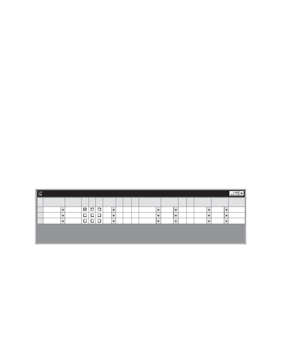
Switcher Description Table
In the Jupiter Switcher Description table, a 480 x 480 block would be
assigned to the “Primary” logical level, and assigned to physical level
“1.” See
Figure 112.
The remaining 32 x 32 block would be defined as the “Secondary”
logical level and also assigned to physical level “1.”
The “Follow” field for the Secondary level would list the name of the
primary logical level. This will prohibit breakaway switching.
Note
The “#IN / #OUT” shown in the Switcher Description table is the overall
system size, i.e., in this example the entry would be 512 x 512 for both
logical levels.
Switcher Description
1
Switcher
Board
2
3
CM1
CM1
PRIMARY
SECONDAR
MAINROUT
MAINROUT
Driver
Binary
Binary
Option
Audio
Follow Level
PRIMARY
VI
RV
MC
#IN #OUT PLvl
Level
DM 400
Off Time
512
512
1
512
512
1
3LI
3LO
None