Installation 154 planning and installation manual – Grass Valley Trinix v.2.4.1 User Manual
Page 154
Installation
154
Planning and Installation Manual
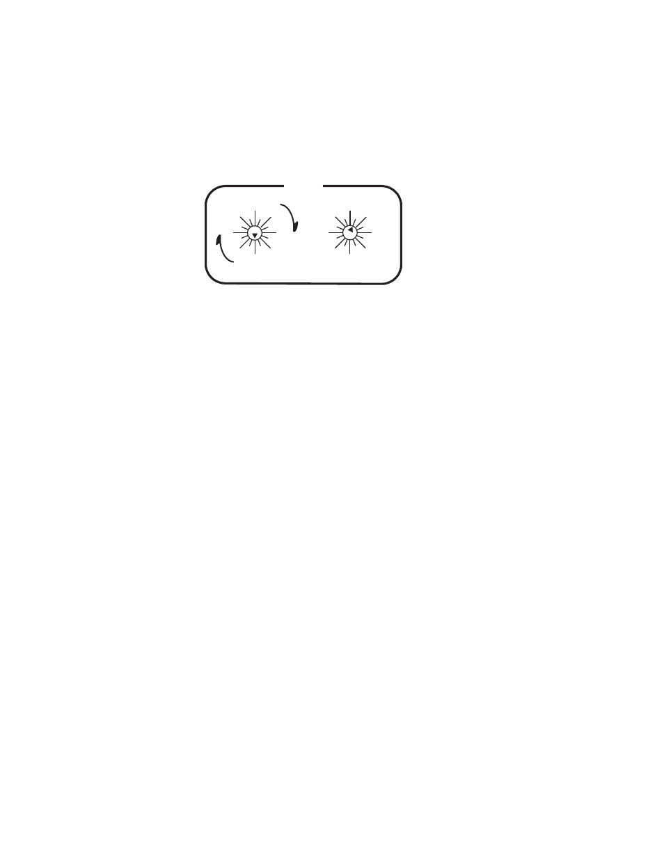
b.
On DV-33512 units only, the rear-panel rotary Level switch must
be set to “Ultra” crosspoint bus, Level 1; i.e., the Super/Ultra
rotary switch must be pointed straight down to “0” and the
adjacent rotary switch must point at “1.” These restrictions do
not apply to DV-33128 and DV-33256 units. See
Figure 87.
3.
On DV-33512 units only, a crosspoint bus cable must be installed
between the power supply chassis and the main chassis.
If there is more than one DV-33512 in the system, the crosspoint bus
must be daisy-chained between units.
The crosspoint bus must be terminated at the farthest point from the
controlling Broadlinx board.
This connection is shown on
.
The crosspoint bus cable is described on
4.
Install LAN components as described beginning on
.
5.
Refer to the SMS 7000 or Encore documentation for control system
configuration details.
0
1
2
3
4
5
6
7
8
9
10
11
12
13
14 15
64
0
16
32
48
80
96
112
0
16
32
48
64
80
96 112
LEVEL
SUPER
ULTRA