Sms 7000 / encore control – Grass Valley Trinix v.2.4.1 User Manual
Page 153
SMS 7000 / Encore Control
Planning and Installation Manual
153
SMS 7000 / Encore Control
These control systems use an Ethernet connection to the Broadlinx
option (NR-33000 Sync/NIC/OPM board).
1.
Set the Trinix “INT XPT CNTL” rear-panel DIP switch to On (switch
closed). See
Figure 85.
In the “internal crosspoint bus control” mode, the Broadlinx board
sends commands to the crosspoint bus.
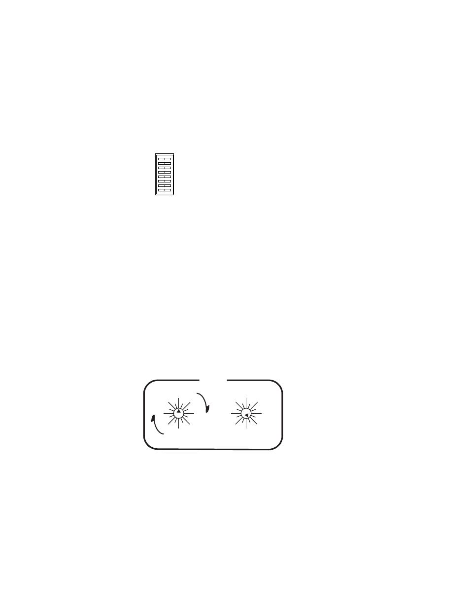
2.
Set Level switches:
Two back-panel rotary switches are used to set the level address of
the router.
a.
For DV-33128 and DV-33256 units, “Super” crosspoint bus
settings are used: the left-hand switch is turned to the
appropriate most significant bit on the “Super” side of the
switch. The least significant bit is set on the right switch. For
example, to set the switcher level at “7” (the factory default for
serial digital video) the left switch would be set at “Super 0”
(straight up) and the right switch set to “7.” See
Figure 86.
Note
On all the Trinix rotary switches, use the triangular arrowhead for
pointing (not the screwdriver slot).
INPUT EXPAND
OUTPUT EXPAND
SYNC REDUNDANT
INT XPT CNTL
60Hz ENABLE
A
B
C
OPEN
CLOSED
0
1
2
3
4
5
6
7
8
9
10
11
12
13
14 15
64
0
16
32
48
80
96
112
0
16
32
48
64
80
96 112
LEVEL
SUPER
ULTRA