Grass Valley Trinix v.2.4.1 User Manual
Page 115
Sync Reference Connections
Planning and Installation Manual
115
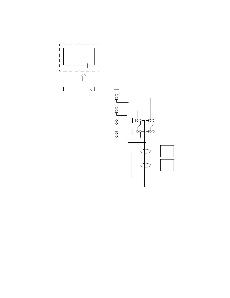
DV-33512 with Dual Sync References and Redundant NR Operation
Figure 54.
In this application, two sync references are looped through the SR-
33500, the Primary NR board, and the Secondary NR board. The NRs
are operated in redundant mode. If the Primary board fails the system
will switch automatically to the Secondary board. If both NRs are
removed, Sync Lines 1 and 2 will automatically switch to the SR board.
Note that Sync Line 1 is always combined with Sync Line 3 and Line 2
combined with Line 4. When configuring the output boards, only “Bus
1” and “Bus 2” are valid selections.
Broadlinx operation is also redundant.
For a discussion concerning which of the two sync references should be
connected to the control system, see
Sync Connection to Control System
Jupiter
Sync 1
2
1 Primary NR-33000
Secondary NR-33000
1
2
3
4
SR-33500
Output
board(s)
on SL1
Output
board(s)
on SL2
Sync Lines
Sync 2
SMS MCPU
Sync 1
or
Encore SCB
OR
Sync Redundant switch = On
“C” switch = On
Sync
1
Some DV-33512 power supply units
are not labelled correctly. See drawing
for correct REF IN con-
nector labelling.
4
3
T
T