Grass Valley Trinix v.2.4.1 User Manual
Page 116
Installation
116
Planning and Installation Manual
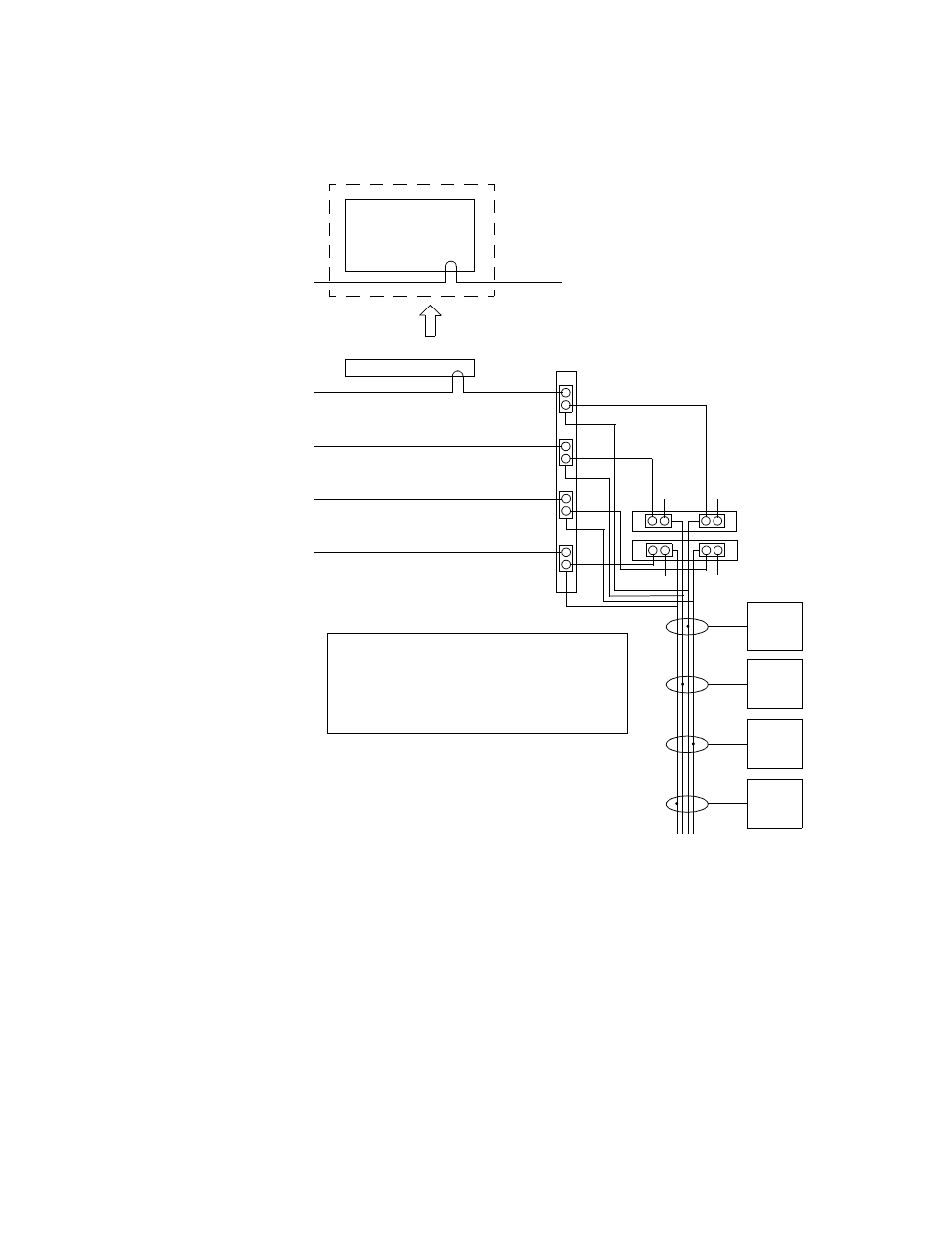
DV-33512 with Multi Sync References and Dual NR-33000
Figure 55.
In this arrangement, all four possible sync references are used. Two NRs
are installed, but not operated in sync redundant mode. The NR board
in the Primary slot will feed Sync Lines 1 and 2; the NR board in the Sec-
ondary slot will feed Sync Lines 3 and 4. If the Primary NR is removed,
Sync Lines 1 and 2 will automatically switch to the SR-33500. If the Sec-
ondary NR is removed, the SR will feed Sync Lines 3 and 4.
For a discussion concerning which of the four sync references should be
connected to the control system, see
Sync Connection to Control System
Jupiter
Sync 1
2
1 Primary NR-33000
Secondary NR-33000
1
2
3
4
SR-33500
Output
board(s)
on SL1
Output
board(s)
on SL2
Output
board(s)
on SL3
Output
board(s)
on SL4
Sync Lines
Sync 2
Sync 3
Sync 4
SMS MCPU
Sync 1
or
Encore SCB
OR
Sync Redundant switch = Off
“C” switch = Off
Sync
1
T
T
Some DV-33512 power supply units
are not labelled correctly. See drawing
for correct REF IN con-
nector labelling.
4
3
T
T