Grass Valley Trinix v.2.4.1 User Manual
Page 127
Duplication and Expansion
Planning and Installation Manual
127
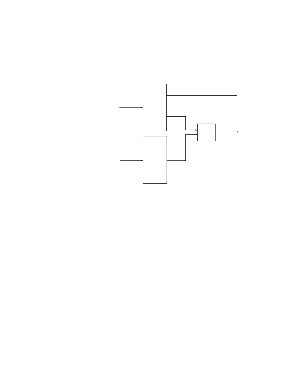
Restricted Input Expansion
In this case one or more output blocks are not combined and are there-
fore not boosted. For example, in the system shown in
Outputs 1-16 of Frame 0 are not combined (and therefore are restricted
to inputs 1-512).
Figure 64.
In this example:
• For SO-33110/33011 and HO-33110/33011 output boards,
the gain for outputs 17-512 would be boosted by closing the
rear-panel Input Expand DIP switches on both chassis and
verifying that the on-board jumpers for that set of outputs
are in the “Expand Enable” position. The location of the
boost jumper on these output boards is shown on
The gain for outputs 1-16 must be held at unity by setting the
on-board jumper for that set of outputs to the “Force
Normal” position; this overrides the rear-panel DIP switch
setting for those outputs.
• For HO-33120/33121 output boards, the gain for outputs 17-
512 would be boosted by closing the rear-panel Input Expand
DIP switches on both chassis and verifying that the on-
board DIP switches for those outputs are closed. The loca-
tion of the DIP switches for these boards is shown on
. The gain for outputs 1-16 must be held at unity by
opening the on-board DIP switch for that set of outputs; this
will override the rear-panel DIP switch setting for those out-
puts.
Frame 0
Trinix
512 x 512
17 - 512
1 - 512
513 - 1024
17 - 512
Dual outputs
32
PE 33016
used as
combiners
Inputs expanded
to 1024 (restricted)
1 - 512
Trinix
512 x 512
Frame 1
1 - 16