Frame number settings, Setting the chassis for input/output blocks – Grass Valley Trinix v.2.4.1 User Manual
Page 146
Installation
146
Planning and Installation Manual
Frame Number Settings
Setting the Chassis for Input/output Blocks
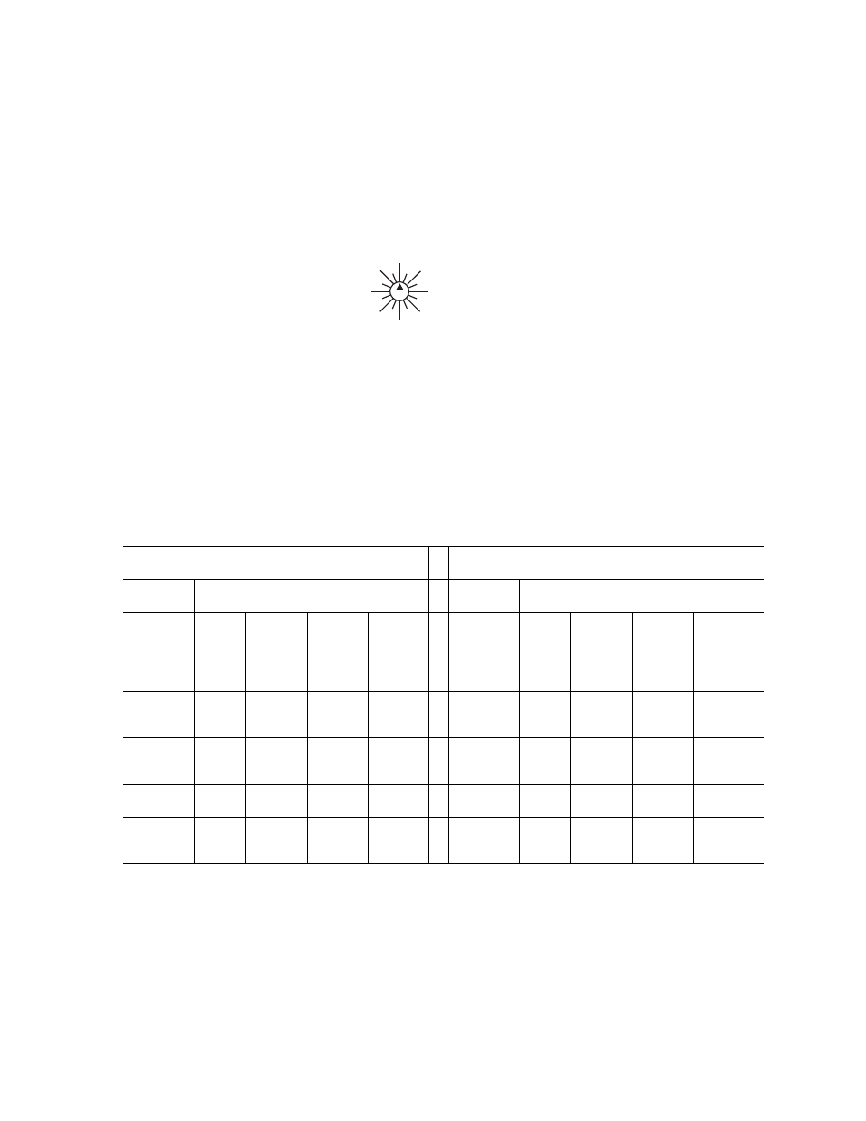
Figure 79.
Up to 16 Trinix chassis can be configured to operate as a single router.
The FRAME rotary switch on the rear panel is used to indicate the rel-
ative position of each individual chassis to the input-output matrix.
The FRAME bits (4) are decoded to determine which inputs and
outputs correspond to the chassis. Refer to the following tables for
input and output relation to the FRAME bits.
Table 28.
DV-33128 (128 X 128)
DV-33256 (256 X 256)
FRAME NUMBER
FRAME NUMBER
INPUTS
INPUTS
385-
512*
5
7
13
15
769-
1024*
5
7
13
15
257-
384*
4
6
12
14
513-
768*
4
6
12
14
129-
256*
1
3
9
11
257-
512*
1
3
9
11
1-128*
0
2
8
10
1-256*
0
2
8
10
OUT-
PUTS
1-
128*
129-
2556*
257-
384*
385-
512*
OUT-
PUTS
1-
256*
257-
512*
513-
768*
769-
1024*
12
0
1
2
3
4
5
6
7
8
9
10
11
13
14 15
FRAME
*For Jupiter-controlled (0-based) systems, subtract one (1) from these input/output numbers.
- LDK 5302 (24 pages)
- SFP Optical Converters (18 pages)
- 2000GEN (22 pages)
- 2011RDA (28 pages)
- 2010RDA-16 (28 pages)
- 2000NET v3.2.2 (72 pages)
- 2000NET v3.1 (68 pages)
- 2020DAC D-To-A (30 pages)
- 2000NET v4.0.0 (92 pages)
- 2020ADC A-To-D (32 pages)
- 2030RDA (36 pages)
- 2031RDA-SM (38 pages)
- 2041EDA (20 pages)
- 2040RDA (24 pages)
- 2041RDA (24 pages)
- 2042EDA (26 pages)
- 2090MDC (30 pages)
- 2040RDA-FR (52 pages)
- LDK 4021 (22 pages)
- 3DX-3901 (38 pages)
- LDK 4420 (82 pages)
- LDK 5307 (40 pages)
- Maestro Master Control Installation v.1.5.1 (428 pages)
- Maestro Master Control Installation v.1.5.1 (455 pages)
- 7600REF Installation (16 pages)
- 7600REF (84 pages)
- 8900FSS (18 pages)
- 8900GEN-SM (50 pages)
- 8900NET v.4.3.0 (108 pages)
- Safety Summary (17 pages)
- 8900NET v.4.0.0 (94 pages)
- 8906 (34 pages)
- 8911 (16 pages)
- 8900NET v.3.2.2 (78 pages)
- 8914 (18 pages)
- 8912RDA-D (20 pages)
- 8916 (26 pages)
- 8910ADA-SR (58 pages)
- 8920ADC v.2.0 (28 pages)
- 8920ADC v.2.0.1A (40 pages)
- 8920DAC (28 pages)
- 8920DMX (30 pages)
- 8920ADT (36 pages)
- 8920MUX (50 pages)
- 8921ADT (58 pages)