Configuration procedure, Figure 57 network diagram, Configure device a: # enter mst region view – H3C Technologies H3C S5560 Series Switches User Manual
Page 225: Manually activate the mst region configuration, Globally enable the spanning tree feature

191
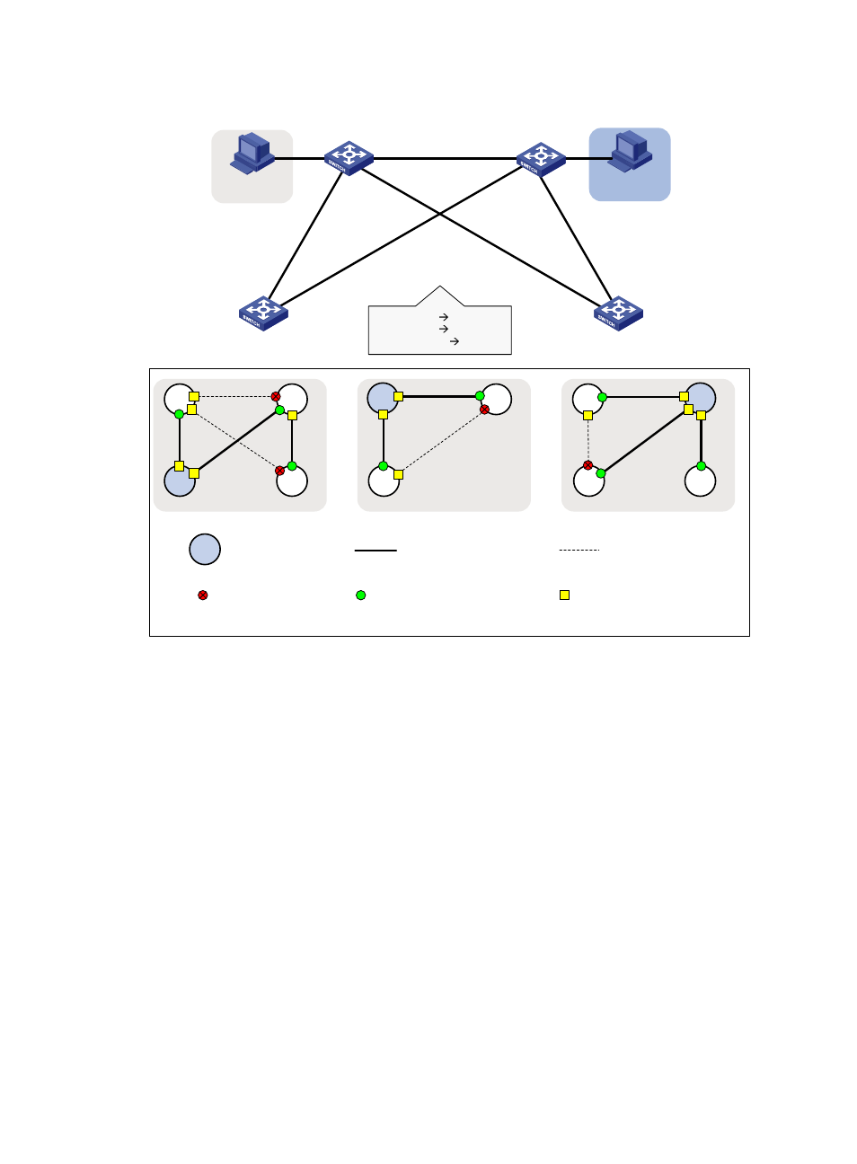
Figure 57 Network diagram
Configuration procedure
1.
Configure Device A:
# Enter MST region view.
[DeviceA] stp region-configuration
# Configure the MST region name, VLAN-to-instance mappings, and revision level.
[DeviceA-mst-region] region-name example
[DeviceA-mst-region] instance 1 vlan 10
[DeviceA-mst-region] instance 2 vlan 20
[DeviceA-mst-region] revision-level 0
# Manually activate the MST region configuration.
[DeviceA-mst-region] active region-configuration
[DeviceA-mst-region] quit
# Configure Device A as the primary root bridge of MSTI 1.
[DeviceA] stp instance 1 root primary
# Globally enable the spanning tree feature.
[DeviceA] stp global enable
VLAN 20
Permit: all VLANs
Per
mit:
VL
AN
40
Pe
rm
it:
al
l V
LA
Ns
Permit: VLANs 20, 40
Permit: all VLANs
Device A
Device B
Device C
Device D
GE
1/0
/2
G
E
1
/0
/1
GE
1/0
/2
G
E
1
/0
/1
G
E
1
/0
/1
G
E
1
/0
/1
GE1/0/3
GE1/0/3
GE
1/0
/2
GE
1/0
/2
VLAN 10
MSTI 1
VLAN 20
MSTI 2
Other VLANs
MSTI 0
VLAN 10
MSTI 2
A
D
Blocked port
Root bridge
MSTI 1
B
MSTI 0
A
C
B
D
A
C
B
C
Topology of each MSTI
Root port
Designated port
Link not blocked
by spanning tree
Link blocked by
spanning tree
- H3C S5130 Series Switches H3C S5120 Series Switches H3C SR8800 H3C SR6600-X H3C SR6600 H3C MSR 5600 H3C MSR 50 H3C MSR 3600 H3C MSR 30 H3C MSR 2600 H3C MSR 20-2X[40] H3C MSR 20-1X H3C MSR 930 H3C MSR 900 H3C WX6000 Series Access Controllers H3C WX5000 Series Access Controllers H3C WX3000 Series Unified Switches H3C LSWM1WCM10 Access Controller Module H3C LSWM1WCM20 Access Controller Module H3C LSQM1WCMB0 Access Controller Module H3C LSRM1WCM2A1 Access Controller Module H3C LSBM1WCM2A0 Access Controller Module
