11 test points – Sundance SMT381 2004 User Manual
Page 77
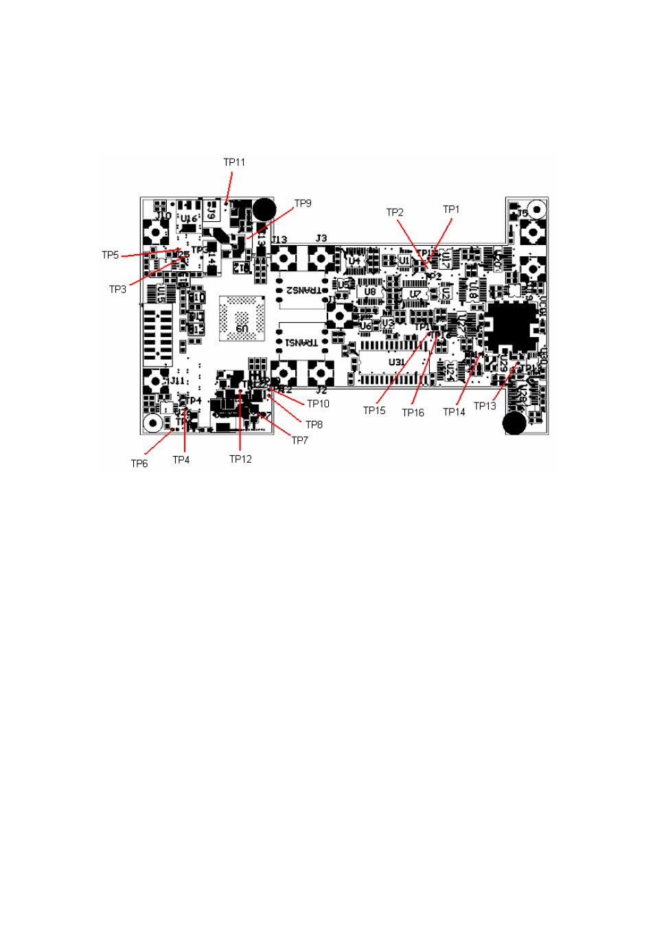
11 Test Points
The following diagram shows all the Test points present on the board.
Figure 69. Test point locations on the SMT381.
TP1 – External Clock positive
TP2 – External Clock negative
TP3 – Daughter Card Connector test point
TP4 – Daughter Card Connector test point
TP5 – Daughter Card Connector test point
TP6 – Daughter Card Connector test point
TP7 – 1V8 test point
TP8 – 3V3_IN test point
TP9 – ECL 5V test point
TP10 – 3V3 test point
TP11 – ECL -5V2 test point
TP12 – Analog 3V3
TP13 – VCO 12V
TP14 – VCO 5V
TP15 – VCO Clock positive
TP16 – VCO Clock negative
This manual is related to the following products: