2 reading and writing registers – Sundance SMT381 2004 User Manual
Page 42
0x5
Reserved
0x6
Reserved
0x7
Reserved
0x8
Reserved
0x9
Reserved
0xA
Reserved
0xB
Reserved
0xC
Reserved
0xD
Reserved
0xE
Reserved
0xF
FPGA Reset
Figure 23. Packet Structure – Defined Commands.
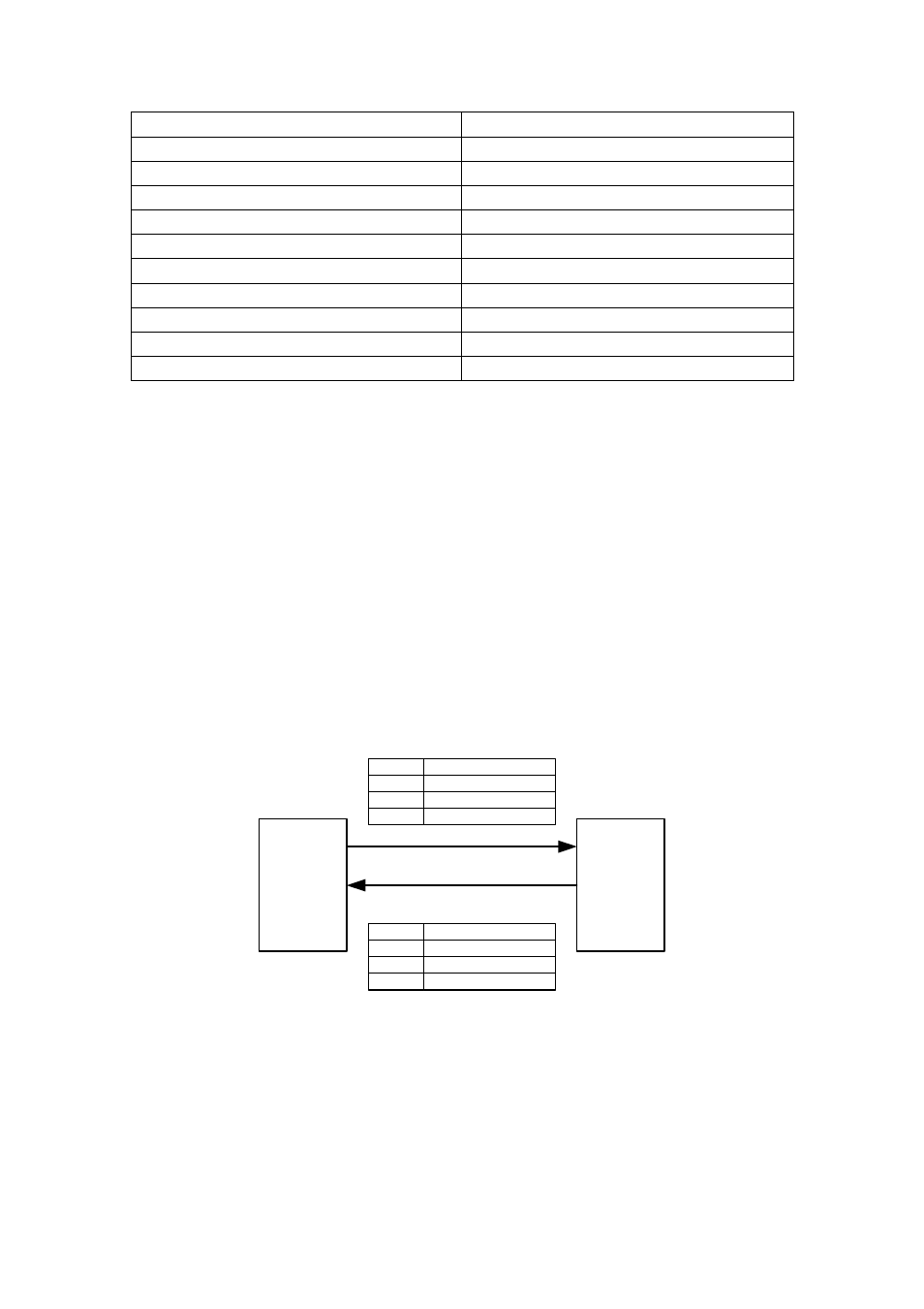
5.2 Reading and Writing Registers
Control packets are sent to the SMT381-VP over ComPort 3. This is a bi-directional
interface and data can be sent to the SMT381-VP over ComPort 3 and also received
over it. ComPort 3 is used to write control information to the SMT381-VP. Data is
written by sending a ‘Write Packet’ (Command 0x1). Data is read by first writing a
‘Read Request’ (Command 0x2) packet containing the address to be read over
ComPort 3. The SMT381-VP will collect the required data and send a ‘Read Packet’
out over ComPort 3 containing the requested data. The format of a ‘Read Packet’ is
the same as that of a write packet. (For the example firmware ComPort 3 is the
designated communications port on the SMT381-VP. This ComPort may however be
connected to any ComPort on the Host.)
Host
Data LSB
SMT391-VP
ComPort 3
ComPort 3
Byte 0
Data MSB
Byte 1
Address
Byte 3
Address / Command
Byte 4
1) Write Packet (0x1), Or Read Request Packet (0x2)
Data LSB
Byte 0
Data MSB
Byte 1
Address
Byte 3
Address / Command
Byte 4
2) Read Packet
Figure 24. Control Register Read Sequence.
Example 1:
Sending 0x1001FFFF over ComPort3 from the Host to the SMT381-VP will Write, to
Address 0x001, Data FFFF
Example 2: