Sundance SMT381 2004 User Manual
Page 29
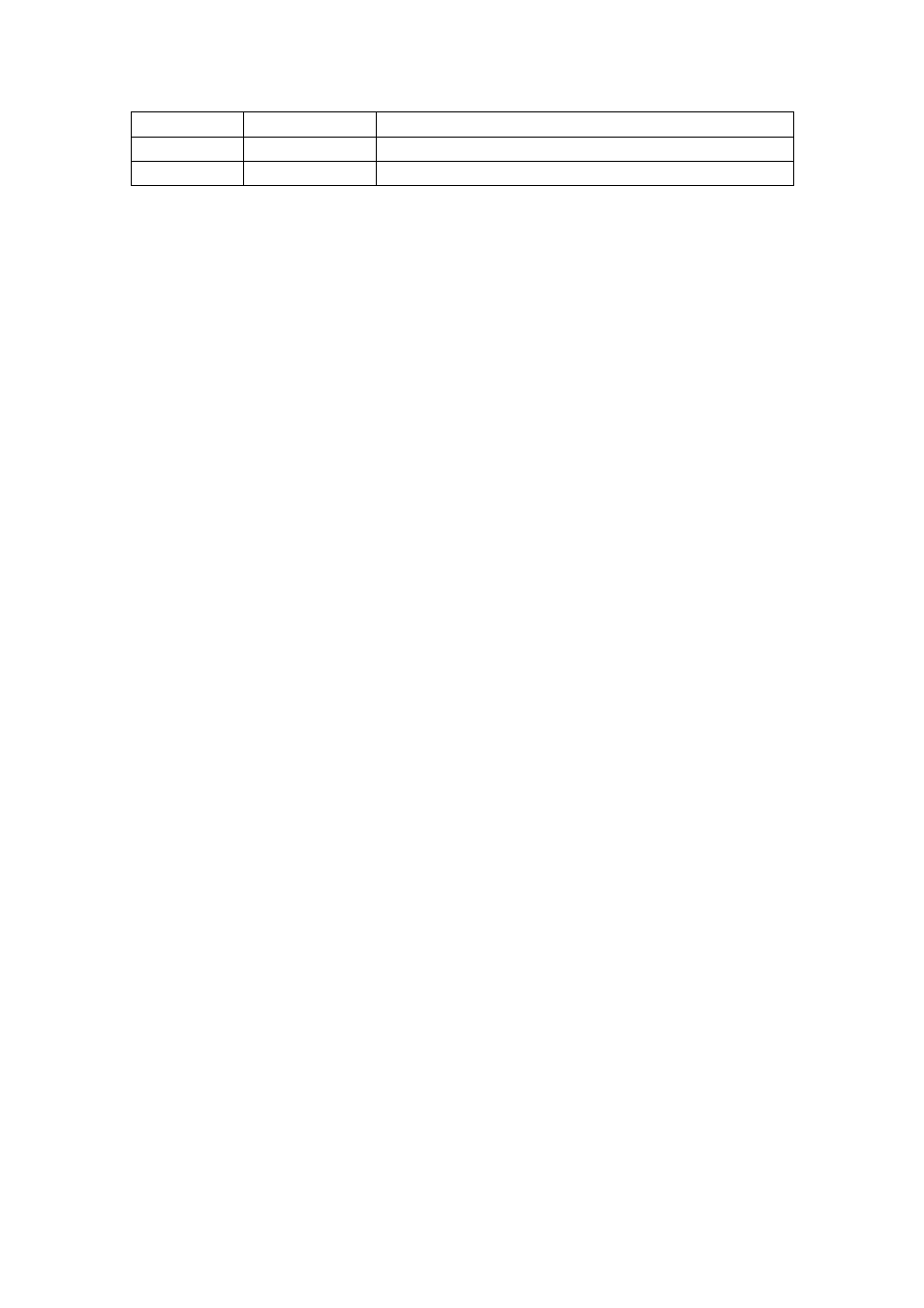
31
TDI
Loop with TDO
32
TDO
Loop with TDI
33
DGND
Digital Ground
Table 2. Daughter Card Interface Power Connector and Pinout.
The following few pages describes the signals on the data connector between the
main module and the daughter card. Bank A on the connector is used for the DAC
Channel A data bus. Bank C is used for the DAC channel B data bus. Bank B is used
for system clock and trigger signals, DAC control signals and general system control
signals. The general system control signals include: clock control interface (for the
clock modules present on the SMT381), daughter card sense signal, daughter card
ID signals, low drop out regulator control signals and daughter card DAC reset signal.
All reserved signals are connected to the FPGA on the main module for future
expansion.