6 clock structure, Figure 3. clock tree of the smt381 – Sundance SMT381 2004 User Manual
Page 17
Clock Tree Setup Interface
There are various clock routing configurations available for the SMT381. This
interface configures the clock tree.
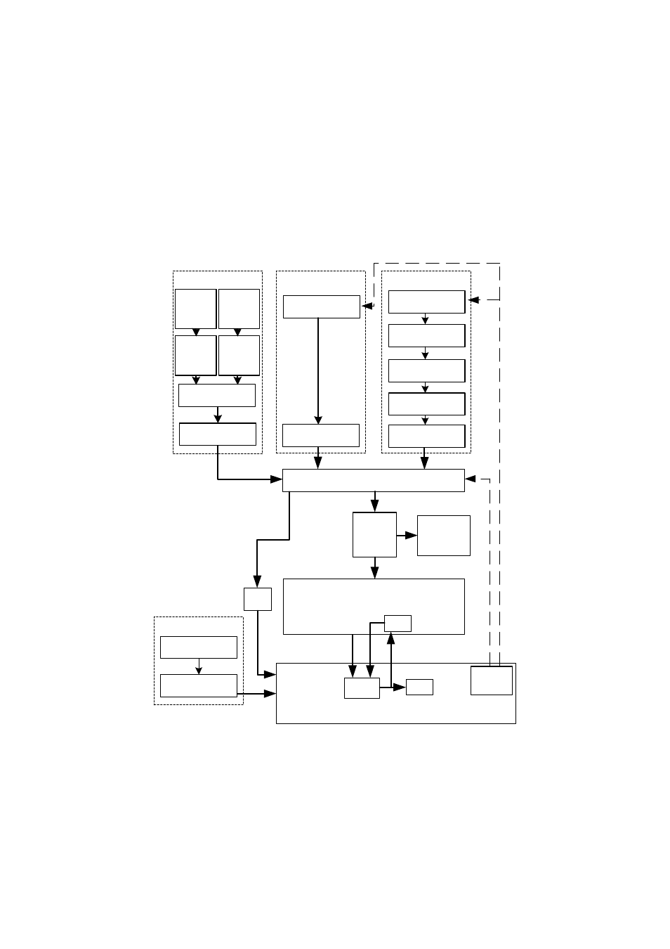
2.6 Clock Structure
There are two integrated clock generators on the module. The user can either use
these clocks or provide the module with an external clock (input via MMBX
connectors). The following figure shows the SMT381 clock tree.
Clk Synth (25MHz -
400MHz)
VCO (600MHz -
1200MHz)
SMT338
PLL
Comparator
Clock
Control
Voltage Controlled
Oscillator
div 2
LVPECL
Buffer
Clk Synth
3:1 Mux with Dual Output
DAC
Clock
Div 8
TTL to LVPECL
External Clocks
Clock Div 2
Ext
LVPECL
Clock
Input
(MMBX)
Loop
Clock
PLL
Data
Clock
External Trigger
LVPECL
Buffer
External Trigger Input
(MMBX)
Fanout
Buffer
DAC clock
output
(MMBX)
Ext RF
Clock
Input
(MMBX)
ECL
Comp-
arator
2:1 Mux
ECL
Reciever/
Driver
Figure 3. Clock tree of the SMT381.
The main clock tree of the SMT381 consists of two clock sources to achieve the
DAC’s full range of input frequencies (DC – 500MHz). The first clock source is a
MICREL clock synthesizer which has a range from 50MHz to 950MHz. This source’s
disadvantage however is that it has a jittery output and thus the clock is not that
stable. Its advantage however is that it can attain a wide range of frequencies,
especially the lower frequencies. The output clock is LVPECL.