3 dac serial setup – Sundance SMT381 2004 User Manual
Page 71
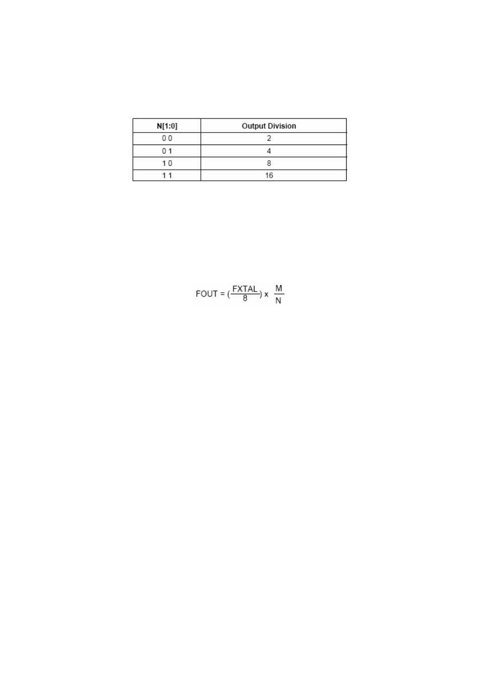
Output division on the clock synthesizer is achieved by the two output division bits
found in the first byte of the clock control register. These configurations are
underneath:
Table 13. Clock Synthesizer Division Setup.
The M count bits are used to configure the clock output frequency given all the
constraints set by the hardware and the clock setup bits. The nine bits can be
programmed with any value from 200 – 400. All the setup bits are then used to
calculate the output with the following equation.
FXTAL = 16MHz (external oscillator)
N = Value in decimal, set up by the division bits.
M = Value in decimal, set up by the M count bits.
Figure 62. Clock Synthesizer Frequency Calculation.
For more information refer to the Micrel datasheets of this part.
10.3 DAC serial setup
A simple 4-wire serial control interface is used to control the DAC. The serial
interface uses pins SERIAL_IN, SERIAL_OUT, SERIAL_CLK and SERIAL_EN.
Programmed settings are stored in a number of registers which are individually
accessible using either a 7-bit (WMM Registers) or 10-bit (DAC Core Registers)
address/control word. Data may be written to or read from each of these registers.
The following figure shows the function timing diagrams for a ‘write’ and ‘read’
operation.