Sundance SMT381 2004 User Manual
Page 36
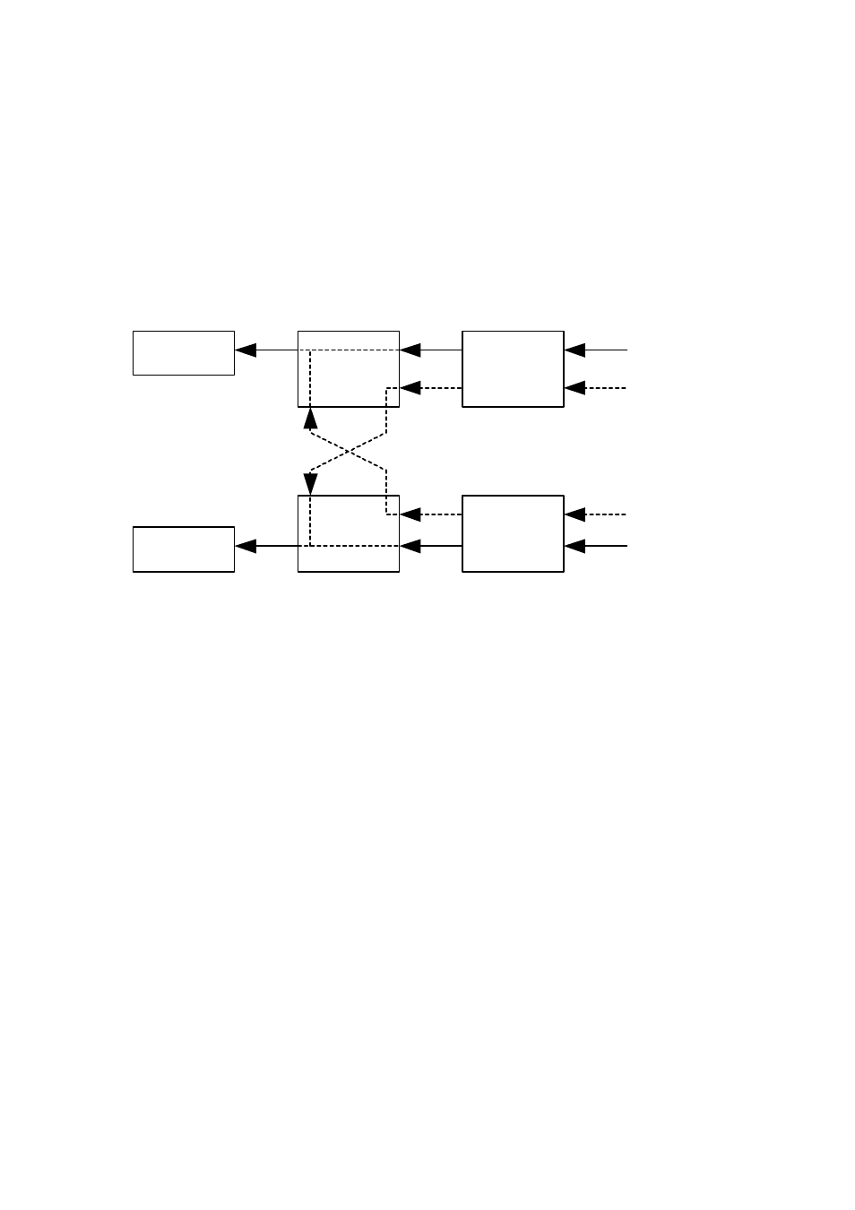
are configured as inputs only. Control and configuration data is received over
ComPort 3. The SHB interface is clocked by the SMT338-VP system clock of 53MHz.
Configuration 2: Either SHB A or SHB B is configured to receive two 16-bit half-
words. The first 16-bits is used for data for channel A and the second 16-bits is used
for data for channel B. (This option is not implemented in firmware.)
The first configuration is ideal for higher speed data transfer. The second
configuration can be used if just one SHB is available on a module that the SMT381-
VP interfaces to. The two possible configurations are illustrated in the following
figure:
SHB A
Interface
Channel A
Data Stream
SHB for
Channel A
SHB B
Interface
Channel B
Data Stream
SHB for
Channel B
32 Bit Channel A
or
16 Bit Channel A and
16 Bit Channel B
32 Bit Channel B
or
16 Bit Channel A and
16 Bit Channel B
Figure 18. Possible SHB Configurations.
The connector used for the SHB interface is a 0.5mm Samtec QSH Type connector.
The full part number for this connector is: QSH-030-01-L-D-A-K
The pinout information for the two possible configurations for both SHB connectors is
given in the following table: