3 description of interfaces – Sundance SMT381 2004 User Manual
Page 24
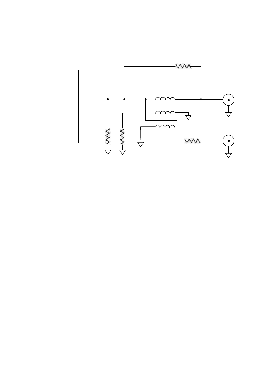
Combined circuit
The two combined:
R3
R3
+
-
0 ohm
0 ohm
TP101
Figure 9. Combined analog output circuit.
Depending on whether an AC or DC coupled version is ordered the board will be
assembled accordingly to either give the AC or DC coupled circuit shown above.
For more information consult the Fujitsu (MB86064) DAC datasheet [6].
2.12 DAC Settings
All DAC settings are controlled and implemented by the 4 wire serial control
interface. The serial interface uses pins SERIAL_IN, SERIAL_OUT, SERIAL_CLK
and SERIAL_EN. Programmed settings are stored in a number of registers which are
individually accessible using either a 7-bit (WMM Registers) or 10-bit (DAC Core
Registers) address/control word. Data may be written to or read from each of these
registers.
For more information consult the Fujitsu (MB86064) DAC datasheet [6].
3 Description of interfaces
3.1 DAC Control Interface
A four wire uni-directional control interface is implemented between the FPGA and
the DAC. This interface is used for clocking configuration information into the DAC.