4 pll configuration – Sundance SMT381 2004 User Manual
Page 74
The first stage receives the update flag and then selects the amount of address bits
and data bits to clock out depending on the values loaded into the
DACSerialSetupReg register.
In the second stage the address stored in the DACSerialAddr is clocked out to the
DAC.
The third stage writes the ‘write’ or ‘read’ bit to the DAC. This bit is the least
significant bit in the DACSerialSetupReg register (DACSerialSetupReg(0)).
In the fourth stage the data present in the DACDataReg register is clocked to the
DAC.
Finally the last stage pulls the ENBALE pin low on the DAC which indicates the end
of the sequence. A few extra clock pulses are necessary after this to complete the
internal register programming.
10.4 PLL Configuration
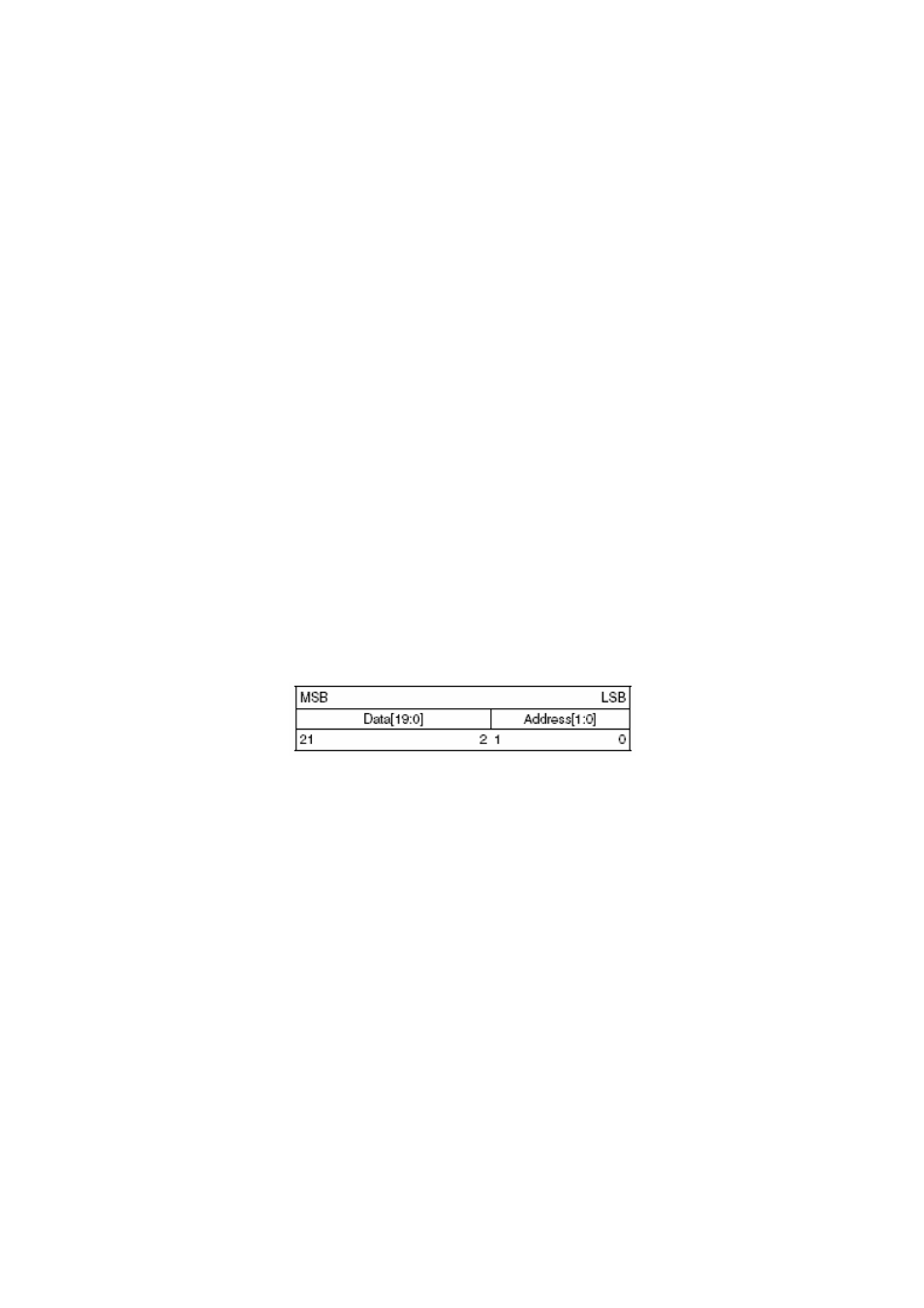
The PLL 22-bit shift register is loaded via a microwire interface. This interface
consists of 3 wires. The shift register consists of a 20-bit Data[19:0] Field and a 2-bit
Address[1:0] Field. The Address Field is used to decode the internal control register
address. When LE transitions HIGH, data stored in the shift register is loaded into
one of 4 control registers depending on the state of the address bits. The MSB of
Data is loaded in first. The register is shown in the following figure.
Figure 66. Register Setup for PLL.
First off the LE line is pulled low and then the MSB of data is loaded onto the Data
line. The Clock line is then driven high and low and a new Data line value is clocked
into the Pll on each rising edge of the Clock line. The Data line is driven with the
registers setup and the Clock line driven high and low until the Data line has reached
the LSB. To end the sequence the LE line is pulled high.
There are two ways to operate the LE line as also shown in the figure below. The
figure also explains how to configure the device.