Sundance SMT381 2004 User Manual
Page 56
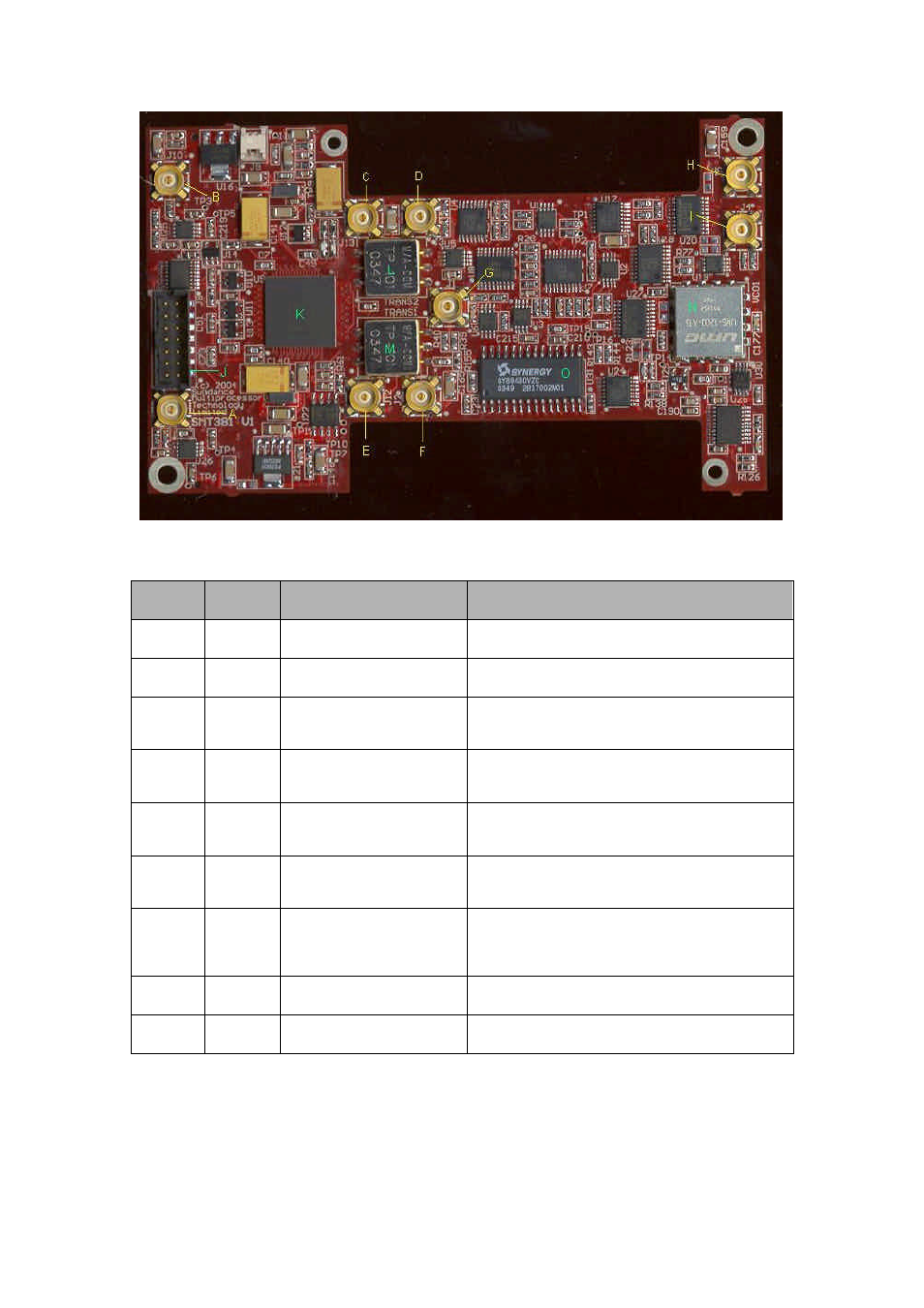
Figure 44. Connector Location on SMT381,
Diagram
Ref
Pcb
RefDes
Description
Notes
A
J11
External Trigger B Channel
LVPECL Signal. Positive on inside of connector.
Negative on outside of connector.
B
J10
External Trigger A Channel
LVPECL Signal. Positive on inside of connector.
Negative on outside of connector.
C
J13
DAC Output B Channel (neg)
Analog Signal. Signal on inside of connector. GND on
outside of connector. For DC Coupling only (differential
signal, split over both connectors).
D
J3
DAC Output B Channel (pos)
Analog Signal. Signal on inside of connector. GND on
outside of connector. For AC Coupling (single ended),
and pos side of DC coupling (differential)
E
J12
DAC Output A Channel (neg)
Analog Signal. Signal on inside of connector. GND on
outside of connector. For DC Coupling only (differential
signal, split over both connectors).
F
J2
DAC Output A Channel (pos)
Analog Signal. Signal on inside of connector. GND on
outside of connector. For AC Coupling (single ended),
and pos side of DC coupling (differential).
G
J1
DAC Test Clock Output
LVPECL output test clock. Copy of clock going to DAC.
Postive on inside of connector, negative on outside of
connector. Used for verification of the clock going to the
DAC.
H
J5
External RF clock input
External Analog input Clock to DAC. Clock on inside of
connector, DGND on the outside of connector.
I
J4
External ECL clock input
External ECL input Clock to DAC. Positive on inside of
connector, negative on the outside of connector.
Table 4. Table of Connector Locations on SMT381.