8 system setup – Sundance SMT381 2004 User Manual
Page 61
8 System Setup
8.1 How to connect the SMT381 to SMT338-VP
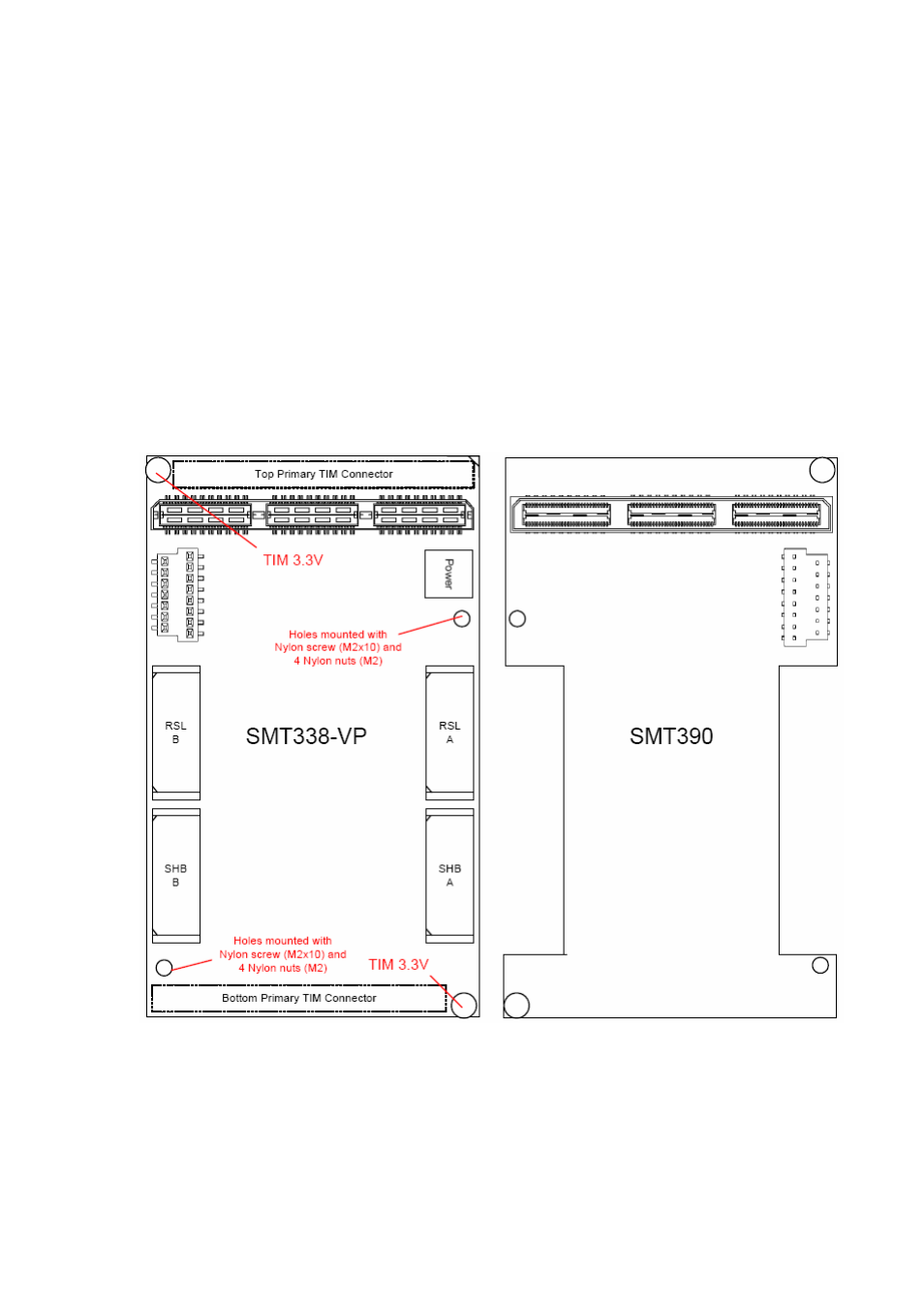
The following diagram shows both the SMT338-VP and the SMT381 (together they
form the SMT381-VP). There are four mounting holes on each board. The two larger
holes on the SMT338-VP are the TIM mounting holes and provide the SMT338-VP
with 3.3V. The two smaller holes add extra stability when the SMT381 is plugged
onto the SMT338-VP (One of these holes on the SMT338-VP carries 1.5V and the
other one 2.5V. These voltages are however not used on the SMT381-VP. For this
reason it is thus safer to use Nylon screws).
SMT390 has the same dimensions and layout as the SMT381.
Figure 46. SMT381 to SMT338-VP Interconnection.
The following fixings are required to connect the SMT381 to the SMT338-VP: