Digital auxiliary components, Installing digital modules – Measurement Computing DataShuttle User Manual
Page 64
6-8 Introduction to Terminal Panels
11-09--01
DataShuttle and DynaRes
To install this resistor the wire at R5 must first be removed. After R5 has been removed, push the resistor
ends through the holes for R5 (from the terminal side) until the resistor lies flat with the panel surface. On
the backside, solder the wires to the holes. Then clip off the extra wire with pliers. The auxiliary component
area in question will now look like Figure 19. This connection does not require any additional traces to be
cut.
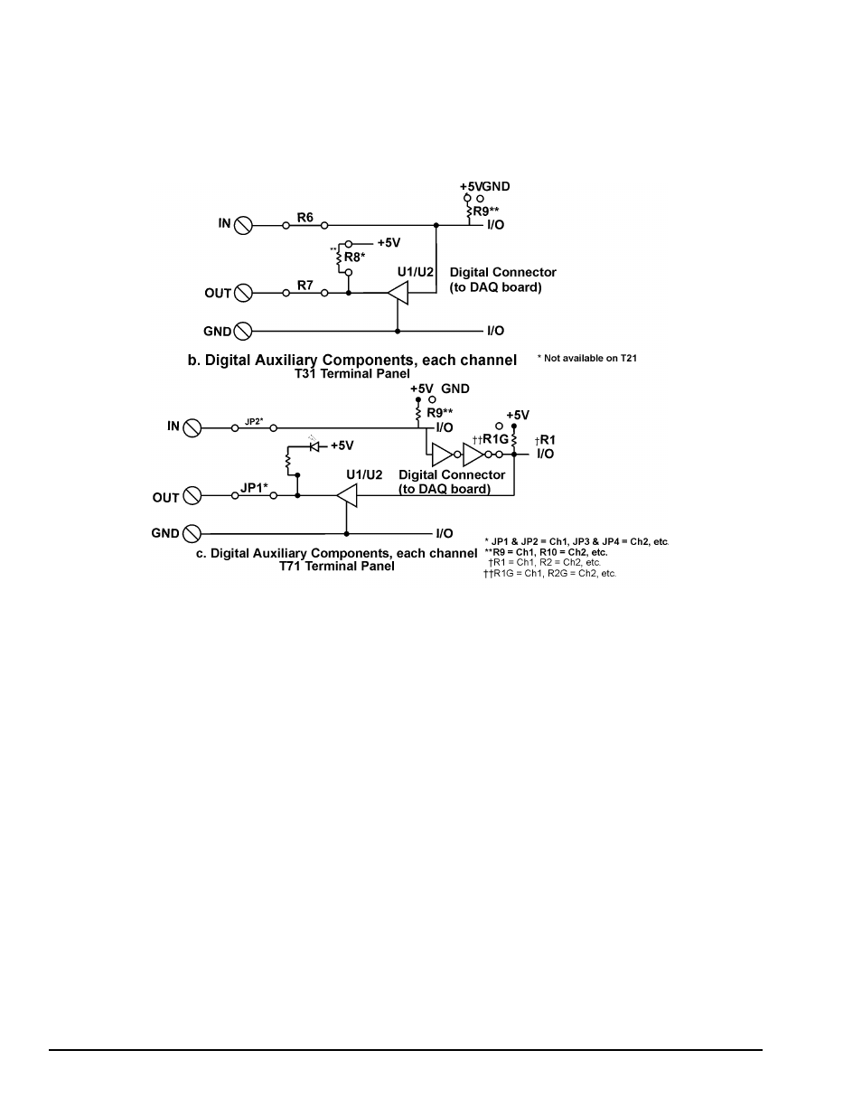
Digital Auxiliary Components
Figure 10 (Cont.) Schematics for Digital Auxiliary Components
Installing Digital Modules
Modules are available to safely connect the digital I/O lines to high voltage AC and DC sources. There are
four basic types:
• AC output: to switch AC power (relay)
• DC output: to switch DC power (relay)
• AC input:
to sense AC voltage
• DC input: to sense DC voltage
The output types are used to switch loads on and off. The input types are used to sense the high/low status
of a signal. All of the modules provide optical isolation between the high voltage and terminations.
These modules may be installed on the T31 and T71 terminal panels. First, remove the jumpers labeled R6
and R7. This disconnects the digital I/Os from the terminals. The module will not fit into the panel until
these jumpers are removed. Then, simply insert the module and fasten a #4-40 nut to the retention screw.
Then, on the back of the terminal panel, solder the leads of the module to the panel.