T71 terminal panel – Measurement Computing DataShuttle User Manual
Page 59
DataShuttle and DynaRes
11-12-01
Introduction to Terminal Panels 6-3
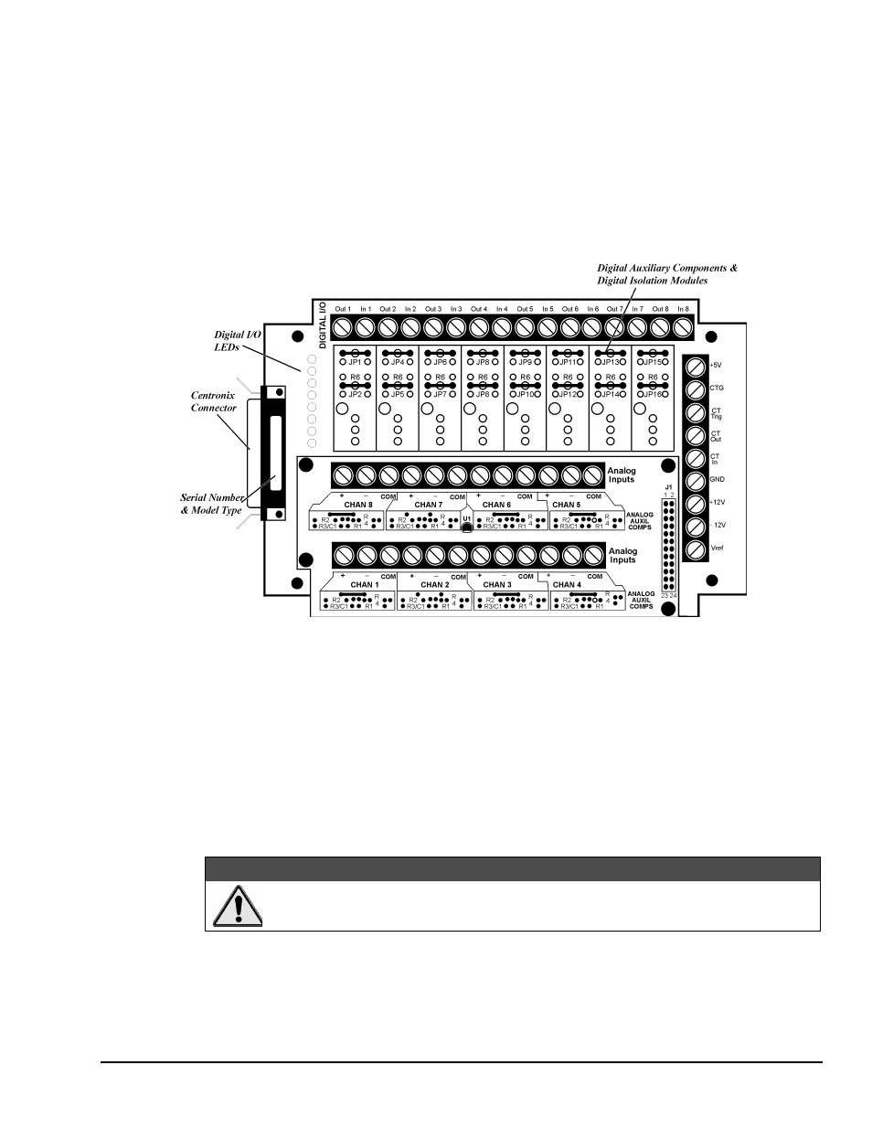
T71 Terminal Panel
Designed for use with the DynaRes data acquisition boards, the T71 terminal panel comes with a 3-ft.,
detachable M-M Centronics cable. The panel features terminals for eight analog inputs and eight digital I/O
lines, with room for up to eight digital opto-isolation modules.
There are three different models of the T71 terminal panel. The T71-TC is optimized for thermocouple
measurements, featuring a large aluminum isothermal plate with screw terminals for eight analog inputs.
The T71-RTD, specifically designed for high accuracy RTD measurements, has signal conditioning set
resistors pre-installed at the factory for use with two- or three-wire RTDs. The T71-GP model, pictured
below, is available for general-purpose measurements.
Illustration of the T71-GP Terminal Panel
Using the Digital I/O Lines – On-unit LEDs show the state of the digital I/O lines. “On” indicates that the
digital input or output is “low,” or that, if a digital output opto-isolator is installed on that channel, it is
energized.
Note that the state of the digital inputs will be “high”, if there is nothing connected. To change a line’s
default to low, a resistor (R1 for Channe1, R2 for Channel 2, etc.) must be moved to an alternate area (R1G
for Channel 1, R2G for Channel 2, and so on).
To Measure Current – There are eight dip switches, marked “Current/Volt,” located under the analog input
daughterboard. To measure current (4-20mA) on a channel, move the corresponding switch to the “Current”
position. This will connect a 24.9
Ω, 0.1% resistor across the + and – inputs for that channel.
:$51,1*
Setting the switch to current may damage the resistors if a voltage in excess of 2.5V is
applied.