Auxiliary analog and digital components, Starting editcal, Analog components – Measurement Computing DataShuttle User Manual
Page 21: Instructions for installing components, Auxiliary components
DataShuttle and DynaRes
11-13-01
DataShuttle - Technical Notes 2-3
Auxiliary Components
Starting EDITCAL
Auxiliary Components are required by some sensors, are used to protect digital signals, or are used to pull
digital outputs to a set level. There are two areas (one digital and one analog) on the DataShuttle for
installing auxiliary components. Schematics of Analog auxiliary components are shown in detail on
page 2-3. Schematics of Digital auxiliary components are shown in detail on page 2-6.
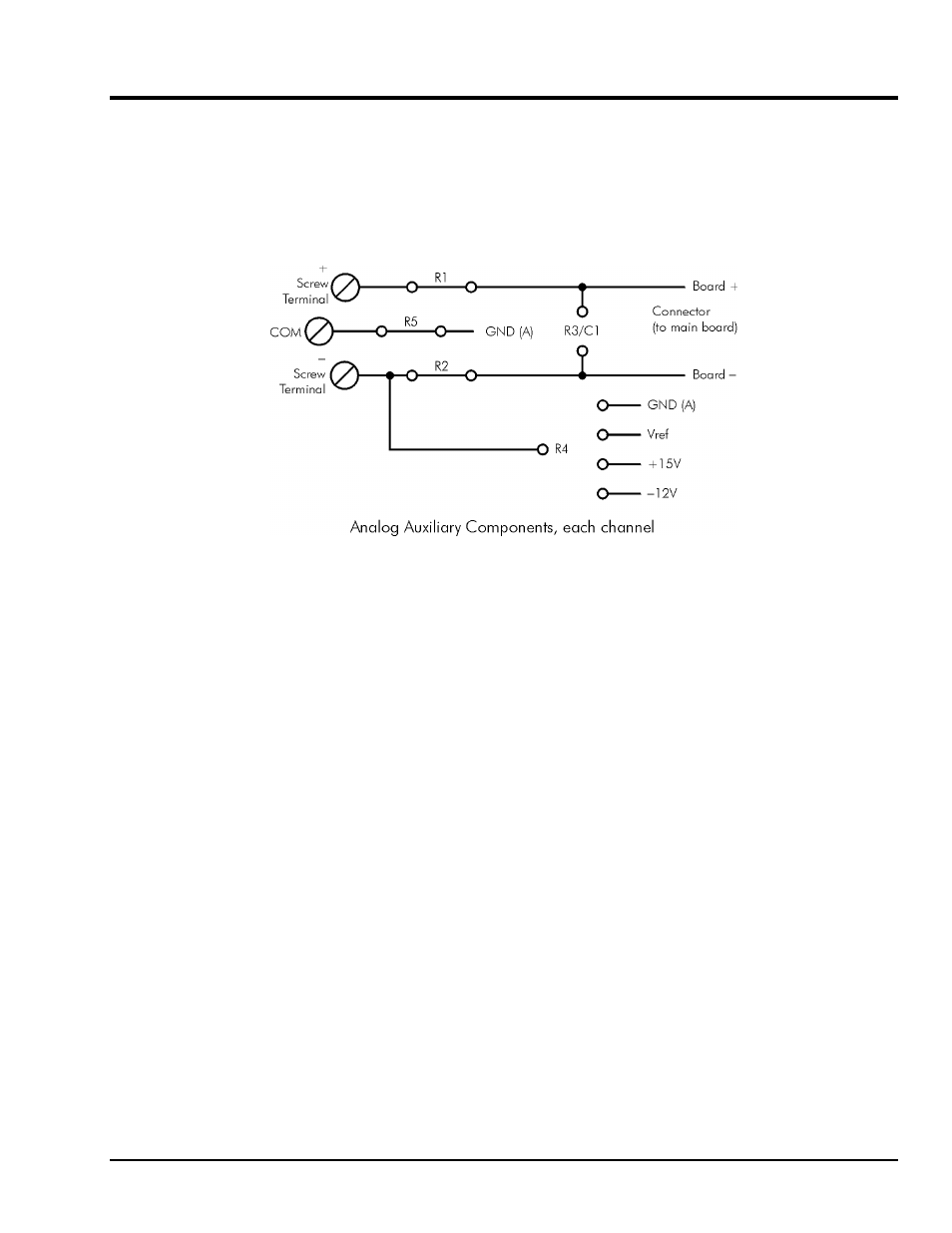
Schematic for Analog Auxiliary Components
Each channel on the DataShuttle has room for its own separate set of auxiliary components. Examples of
their use can be found in the following pages and in the Applications Reference Section.
Analog Components
Instructions for Installing Components
Most common sensors can be connected without the use of auxiliary components. Some of the sensor
installations (bridges, RTD circuits, voltage dividers and current sensors), however, require auxiliary
components. These components can be installed on the DataShuttle for convenience. This requires soldering
and some familiarity with electronics. In the examples in the Applications Reference Manual, and the
following, the component locations are shown but not the component values; you must calculate the values
if they are not supplied with the sensor.
The first step is to remove the daughterboard from the unit, as you will need full access to it for soldering on
the auxiliary components. To do this, simply remove the four screws in the corners of the daughterboard
and lift it off of the DataShuttle.
When using analog auxiliary components R1, R2, and R5 you must cut the shorting metal trace that
connects the two ends of the line together before installing any of the components in these locations. Use a
sharp knife to carefully slice through the trace without cutting additional traces. In the case of R5 this is a
plastic covered metal wire. Diagrams of the auxiliary component area, hole functions, and connection
possibilities are shown on the following page.
Note: Analog auxiliary components are not available on DS-5B models.