Examples, Example 1: current sense resistor, Example 2: 3-wire rtd components – Measurement Computing DataShuttle User Manual
Page 23
DataShuttle and DynaRes
11-13-01
DataShuttle - Technical Notes 2-5
Examples
Example 1: Current Sense Resistor
The DataShuttle can measure currents up to 50 mA directly. A 24.9 Ohm precision resistor needs to
be installed in the auxiliary component area to do so. This connection for current measurement is shown
below. (To see how this connection adds to the circuit, refer to Figure on page 2-3.) R3 is used as a shunt
resistor across the positive and negative lines of the channel in use. To install this resistor, push the resistor
ends through the holes for R3 (from the terminal side) until the resistor lies flat with the panel surface.
On the backside, solder the wires to the holes, and then clip off the extra wire with pliers. This connection
does not require any additional traces to be cut. Be sure to select current measurement in the software
package that you are using. This installation allows the measurement of voltage across the resistor and the
conversion of this measurement to current using the equation V=IR. Observe the power rating of the resistor
you install at R3. Space is provided for a 1/4 Watt resistor.
Figure 6. Current Measurement Connection
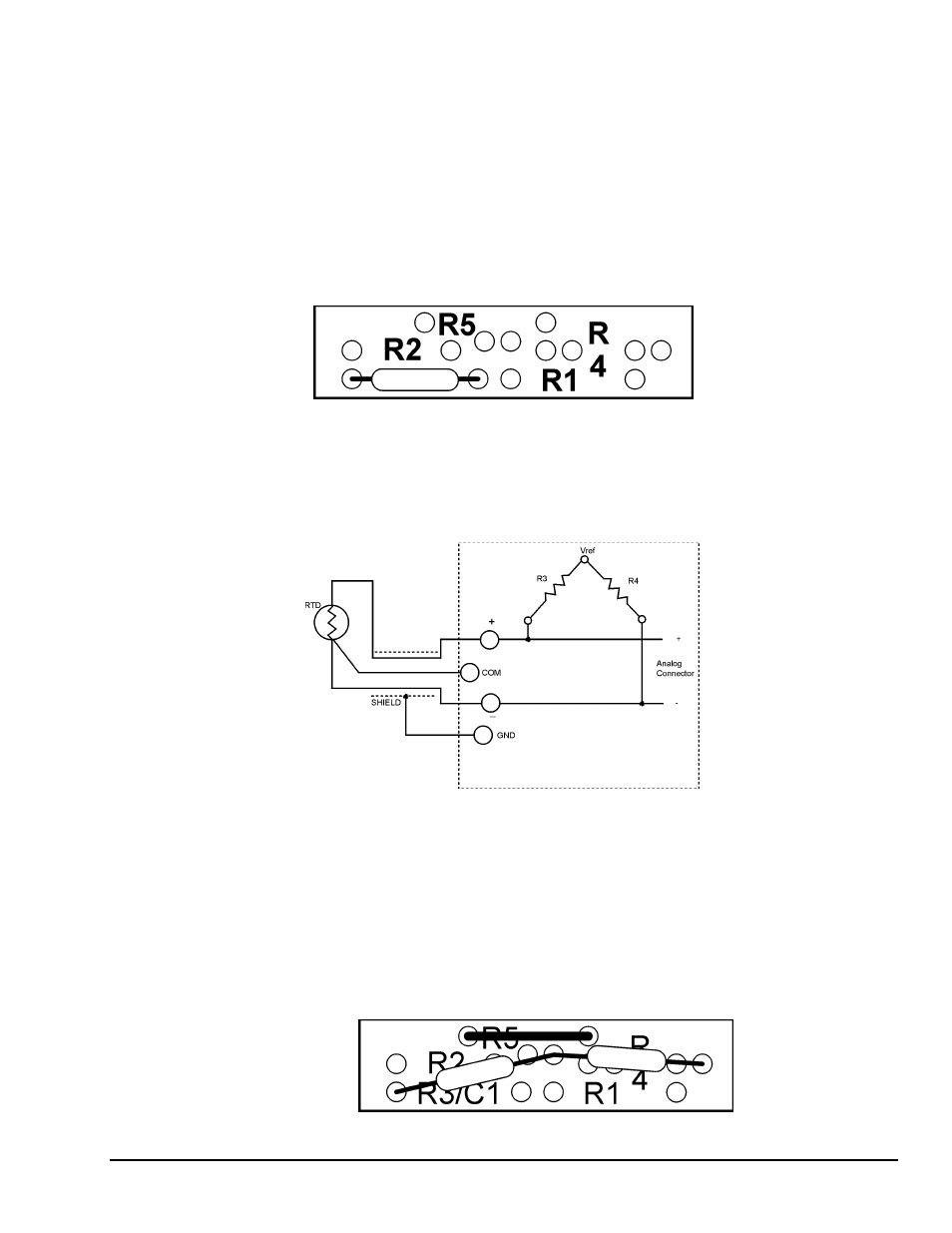
Example 2: 3-Wire RTD Components
The most popular connection for RTDs is the three-wire type. This sensor requires the installation of
resistors R3 and R4 except for these DataShuttle RTD model, where both resistors are already installed.
Consult Set Resistor Values on page 2-14 for R3 and R4 values.
.
3- Wire RTD
Figure 7. 3-Wire RTD Components
However, if you need to install these resistors yourself then do the following: Figure 4 and Figure 5 show
the possible locations of R3 and R4. Figure 1 will show you that R3 and R4 need to be connected
as in Figure 14. R5 is already in place and should not be removed. To install these resistors push the
resistor ends through the holes for R3 and R4 as shown in Figure 4 (from the terminal side) until the resistor
lies flat with the panel surface. If two wires cannot fit into the Vref hole then one wire may be soldered
to another that is already inserted. On the back side solder the wires to the holes. Then clip off the extra
wire with pliers. The auxiliary component area in question will now look like Figure 8. This connection
does not require any additional traces to be cut.
Figure 8 . 3-Wire RTD Connection