Example 3: ground loops, Wiring analog outputs on the datashuttle, Voltage outputs – Measurement Computing DataShuttle User Manual
Page 24
2-6 DataShuttle - Technical Notes
11-13-01
DataShuttle and DynaRes
Example 3: Ground loops
Occasionally there is an installation where the ground connection is made at the sensor, but it is not reliable.
The solution to this “intermittent” ground is to replace the COM to GND(A) jumper wire at R5
(Figure on page 2-3) with a 10 Megohm, 5%, 1/4 Watt resistor. This provides a ground reference for the
analog inputs in question, but allows very little ground current to flow. In very noisy environments with
intermittent grounds, a smaller resistor may be used if the readings are erratic.
To install this resistor the wire at R5 must first be removed. After R5 has been removed push the resistor
ends through the holes for R5 (from the terminal side) until the resistor lies flat with the panel surface.
On the backside, solder the wires to the holes. Then clip off the extra wire with pliers. The auxiliary
component area in question will now look like Figure 9. This connection does not require any additional
traces to be cut.
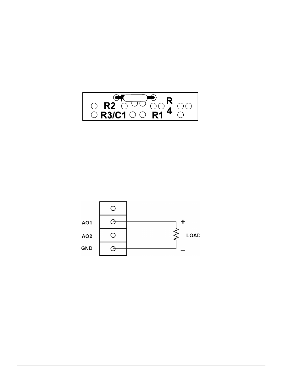
Figure 9. Ground Loop Connection
Wiring Analog Outputs on the DataShuttle
Voltage Outputs
Voltage outputs can drive a wide variety of controllers, amplifiers, and other devices. Figure 9a shows the
standard way in which the Data Shuttle analog output terminals are connected to a load when the “Voltage
Output” option has been selected in the software.
Note: The load resistance should be at least 1000 ohms to guarantee that the output will not have to source
more than 10 mA.
Figure 9a. Voltage Output