High power optically isolated digital input, High power optically isolated digital, Input …… 14-2 – Measurement Computing DataShuttle User Manual
Page 116
14-2 Digital I/O
11-12-01
DataShuttle and DynaRes
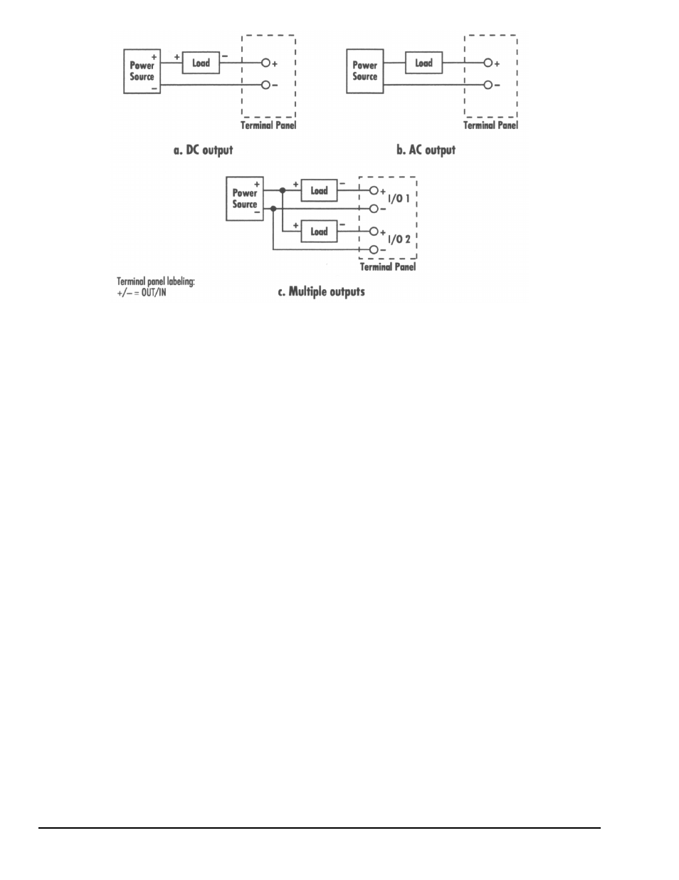
Figure 14-1. High Power Output Connections
If the load is a DC load, such as motor, pump, or valve, it may have a polarity indication. Be sure to
connect the terminals correctly (see illustrations) to avoid damage. Some DC loads, such as lights and
heaters, often do not have polarity. You must still be careful to connect the power source correctly so that
the SSR can switch the load.
There is no polarity to watch when connecting AC loads or power sources to the screw terminals. Ignore
the terminal labels for AC loads.
The power source indicated in the figure might be 120 Volts AC to power heaters, lights, and pumps, 24
Volts DC to power pumps and relays, or 5 Volts DC to power relays and lights. The power source rating is
determined by the requirements of the load. Be sure the output SSR can handle the current and voltage the
load requires.
Figure 14-1c shows how to share a single power source among several loads. This occurs frequently. The
number of loads that may be shared is limited by the current capability of the power supply. This only
works, of course, if all the loads have the same voltage rating.
Be sure to set each line to the correct input or output condition in the software you are using.
These components require approximately 20 milliseconds to switch.
High Power Optically Isolated Digital Input
(For T31 terminal panels)
Digital input can be detected with any DynaRes board that has digital I/O capability.
Connections to the screw terminals for DC input signals are shown in Figure 14-2. There are two basic
types, contact closure inputs shown in Figure 14-2a, and signal inputs shown in Figure 14-2b. AC input
connections are shown in Figure 14-3. The connections are almost identical to Figure 14-2 for DC.
For contact inputs, a power source provides a voltage that, when connected to the screw terminals, is
detected as a high level by the SSR. Because the SSR inverts the input, it appears as a low input to the data
acquisition board. The switch interrupts the power source when it is open, resulting in a low level input to
the SSR and a high level input to the data acquisition board.
Signal inputs connect directly to the screw terminals. They must be capable of driving the input SSR. The
PSAC3-W detects a high level input for voltages greater than 90 Volts AC or DC. The maximum voltage
you should apply is 140 Volts AC or DC. It draws 11 milliamps input current maximum. The PSAC1-W
detects a high level input for voltages greater than 10 Volts AC or DC. The maximum voltage you should
apply is 32 Volts AC or DC. It draws 25 milliamps maximum.