Previously in use, Physical board installation, Terminal panel connections – Measurement Computing DataShuttle User Manual
Page 42
4-2 Installing the DynaRes
11-09-01
DataShuttle and DynaRes
Previously in Use
If, on the other hand, your board has been in use previously in another computer, or if your company uses
its own proprietary software, the present switch positions might differ from the factory settings.
If your company uses such a program, making changes to factory switch settings might be necessary to
accommodate it. Please consult the administrator of your internal system, or the provider of third party
software, to determine their recommendations for any unusual switch setting.
To check and restore the factory values, please read “Board Number Switch Settings” on 4 – 4 in this
chapter.
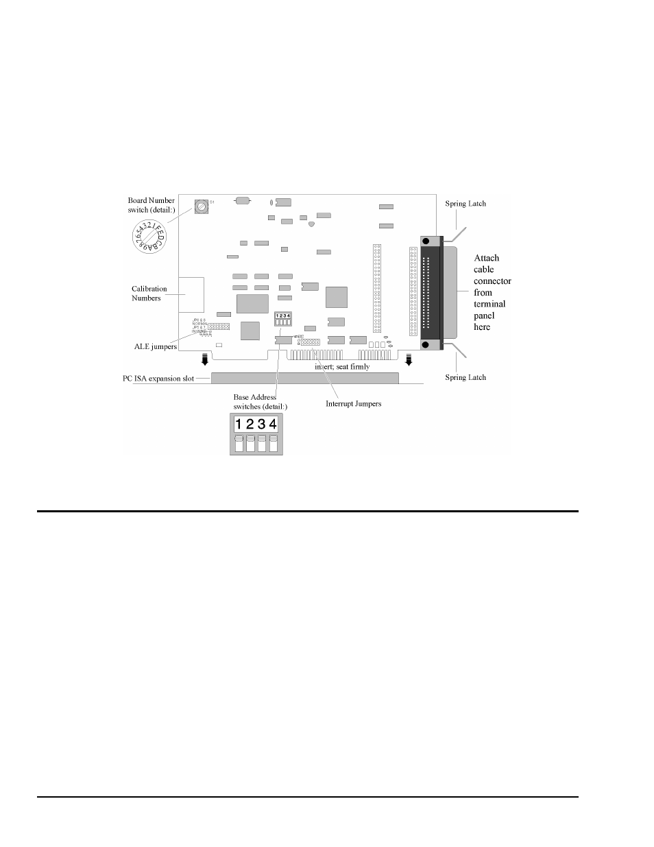
Illustration of DynaRes Data Acquisition Board, Showing Physical Installation
Physical Board Installation
Installation consists of inserting the board into an open peripheral (expansion) slot inside your computer.
(There are, for example, five available slots in the IBM PC, and eight in the IBM XT or AT. IBM and other
companies sell expansion chassis that can accept even more analog cards. Our software supports as many as
15 boards at one time.)
Terminal Panel Connections
When using a terminal panel with the DynaRes (to connect external devices: sensors and digital
input/output) you are going to use the provided Centronics cable.
Each cable can conduct eight analog input channels and eight digital I/O lines from your DynaRes to a
single terminal panel.
One Terminal Panel, One Cable – A DynaRes 8, using eight analog input channels, requires one
Centronics cable for connection to one terminal panel (this also allows the use of eight digital I/O lines).
Two Terminal Panels, Two Cables – A DynaRes 16, using 16 analog input channels, requires two
Centronics cables for connection to two terminal panels (to handle two “banks” of eight analog inputs:
Analog Input Channels 1- 8, and Analog Input Channels 9-16).
(Refer to “Pinouts,” in Chapter 5 of this manual, for a description of the signals at the connectors.)