Current output, Current output …… 13-12 – Measurement Computing DataShuttle User Manual
Page 112
13-12 Analog Input & Output
11-12-01
DataShuttle and DynaRes
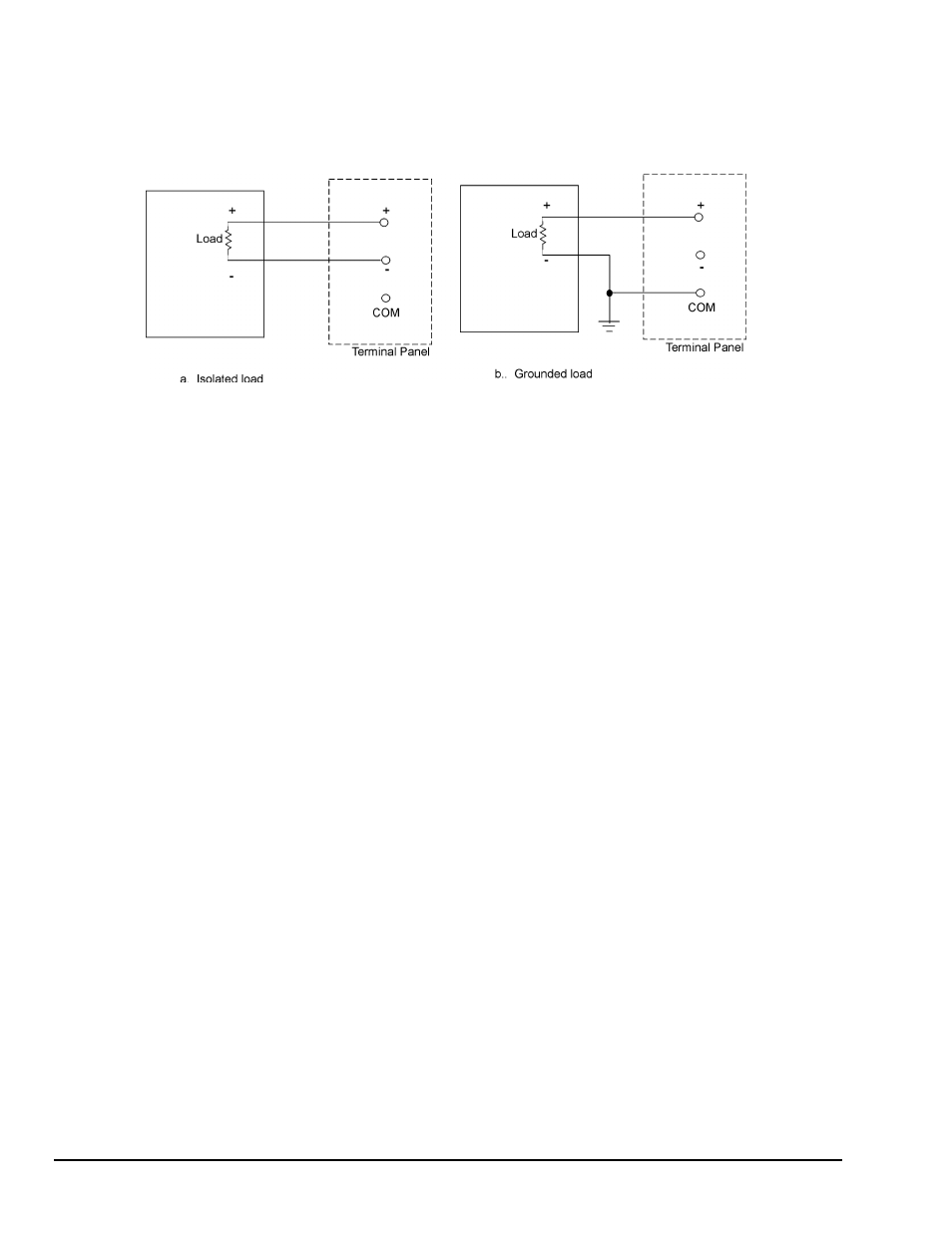
Figure 13-8b shows a connection that may by used where the load is already connected to ground. This
connection is not recommended, however. Voltage drops in the ground between the computer and the load
will appear as error voltages in the signal. This means that for maximum accuracy you should have a load
that is isolated from ground. In some cases this is not possible. If you have to use the connection of Figure
13-8b, make the ground return wire a large gauge, such as AWG 18 or larger. This will minimize errors
due to current flowing in the wire.
Figure 13-8. Voltage Output
Current Output
Most current outputs connect to current loop devices, which are often controllers. Almost all current loops
are 4 to 20mA. If you have a device with another range, refer to Figure 13-9d.
A 4-20mA current device has the advantage of running the power and signal over the same pair of wires.
Also, current signals are much less susceptible to noise pickup than voltage signals.
The circuit in Figure 13-9a is the most common way to connect a current loop. The power is supplied from
the +12 Volt source on the terminal panel. Many loads may be driven from one supply. The negative
terminal of each load must be independently tied to the “+” output terminal. If the requirement cannot be
met, the circuit of Figure 13-9c must be used.
The 12 Volt source connects to the computer’s power supply. If you are connecting a large number of
current loops, you may want to use an external supply as in Figure 13-9b. This connection is otherwise
identical to Figure 13-9a.
Figure 13-9b is a advantageous when a load requires a large voltage. With a 12 Volt source, as in Figure
13-9a, the voltage drop across the load must be less than 9.4 Volts. The voltage at the analog output must
be at least 2.6 Volts. The voltage at the analog output must be at least 2.6 Volts for the output to operate
normally: 12 – 2.6 = 9.4 Volts. To be on the safe side you should allow for the +12 Volts supply to be low
by as much as 1 Volt. This leaves only 8.4 Volts across the load. The load resistance must, therefore, be
less than 420 Ohms: 8.4 Volts
÷ 20mA = 420 Ohms. For loads with a higher resistance, the supply voltage
must be higher. You can connect a power supply up to 50 Volts.
Use voltages higher than 12 Volts only when necessary. If the output is accidentally set to voltage instead
of current with more than 12 Volts connected, the board will be damaged.
Use the connection of Figure 13-9c when the load is connected to ground. Unlike Figure 13-8b for voltage,
the return wire to the “COM” terminal in Figure 13-9c is not necessary, and in fact, may degrade
performance. Voltage drops in the ground wire do not affect the accuracy of the current supplied to the
load. The connection to the “COM” terminal should be used only when the ground connection at the load
is not reliably connected to the computer ground.
You must be careful not to have a large voltage drop between the computer ground and the ground of the
load. If the difference in the two grounds is large it will either reduce or increase the voltage across the “+”
and “-“ terminals of the board. If the voltage is less than 2.6 Volts, the current output won’t operate
properly. If the voltage is more than 50 Volts, the current output may be damaged.
The disadvantage of this connection is that each load requires its own power supply. The power from the
terminal panel may not be used because it does not have a separate negative return.