Rtds, Rtds …… 13-7 – Measurement Computing DataShuttle User Manual
Page 107
DataShuttle and DynaRes
11-12-01
Analog Input & Output 13-7
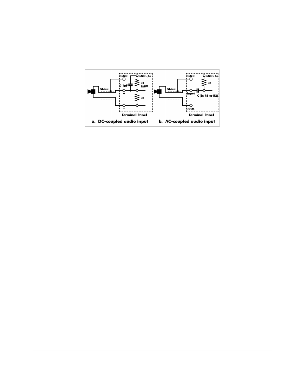
The capacitor C and the resistor R3 form a high-pass filter network, which specifies the lowest frequency
audio signal, which will be transmitted to the data acquisition board. The lowest frequency point is given
by the equation:
F= 1
÷ (2πR3C)
Install capacitor C in location R1 or R2. Select R3 to be large in comparison to the output impedance of
your audio transducer, and then you select C to set the lowest frequency which you wish t digitize with
your data acquisition board. Refer to your audio transducer manual for details.
Figure 13-4. Audio Input Configurations
RTDs
An RTD (Resistance Temperature Detector) changes resistance with temperature. The most common type
is made of platinum because it is highly stable and its resistance change is linear. RTDs are connected like
resistors, but there are some variations for three wire and four wire types. The most common resistance for
platinum RTDs is 100 ohms at 0ºC. There are other popular values ranging from 50 to 1000 ohms.
Figure 13-5a is an example of the connections for a two-wire RTD. This is the simplest connection. The
precision voltage reference can be used as a power source. Auxiliary component R3 must be a precision,
stable resistor. R4 has no effect with a two wire RTD. Install the lead of R3 that is near the analog
terminals, in the reference voltage hole. This circuit can suffer from errors in long sensor wires because of
wire resistance.
Figure 13-5b overcomes the wire resistance problem with a three wire RTD. R3 and R4 are equal so the
currents in the signal wires (connecting to the + and – terminals) are equal. The voltage drops in the two
signal wires are equal (so they cancel each other) because the signal wires have equal resistance. Only R3
must be high precision and stable. Consult tableset resistor values on page 13-6.
Figure 13-5c uses a four wire RTD for the highest precision. It does not rely on the signal wires being of
equal resistance. R is a precision stable resistor. The resistor R does not install on the panel. The values
for R3, the set resistor, are shown below. Keep the voltage drop across the RTD below 50 millivolts. This
keeps heating less than 50 microwatts and subsequent temperature errors negligible.
Accuracy and resolution are shown for 16-bit boards in the following tables.