Pulse counting, Cascaded counter/timers – Measurement Computing DataShuttle User Manual
Page 118
14-4 Digital I/O
11-12-01
DataShuttle and DynaRes
Figures 14-2c and 14-3c show switches connected as in Figure 14-2a and 14-3a, except that they share a
common power source. Since the input current requirements are minimal, you can connect almost an
unlimited number of switches with a single power source.
Be sure to set each line to the correct input or output condition in the software you are using.
These components require approximately 10 milliseconds to switch. Because of this delay, they are not
suitable for use with counter/timers.
Pulse Counting
Counter/timers available on your data acquisition boards may be used for pulse counting, pulse output,
frequency measurement, or timing. Each counter/timer has four I/O lines associated with it. They are used
for inputs and outputs. The four I/O interface lines, the internal software line equivalents, and the various
modes can all be used together to give a great deal of flexibility. A very simple but common example is
that of counting pulses. (Note that the low and high power digital isolation modules should not be used in
conjunction with the counter/timers, as these modules switch too slowly for counter/timer applications, and
will likely result in erroneous counts.)
For pulse counting, only the input line of the counter/timer is used. You may make connections using the
above diagrams for DC inputs. Do not use optical isolation components for this application.
In the software, you must set up the counter/timer. The external input line must be enabled. You should
set the full count to 65,535, as high as possible (or to zero under certain circumstances). In most cases the
output, gate, and trigger lines are not used. The software should gate and trigger the counter/timer
Internally, you might choose to use the gate, for instance, to block pulses during certain events signaled by
another digital input. If so, connect that digital input to the gate and enable the external gate input.
You can set the counter/timer to count up from 0, or down to 0. The total number of pulses can be read
from the counter at any time. You may have the software reset the count to 0 periodically to start over.
The counter/timer lines are labeled on the panel below the I/O numbers as “CT1”,”CT2”, and so on. Each
external counter/timer line is also labeled as “IN”, “OUT”, “GATE”, and “TRIG”.
Cascaded Counter/Timers
You may wish to count more than 65,535 pulses, the limit of one counter/timer. This can be done simply
by cascading the output of one counter/timer into the input of another. The same thing would allow timing
longer than 0.032 seconds in a timing application. This can be done by using more than one board with a
counter/timer.
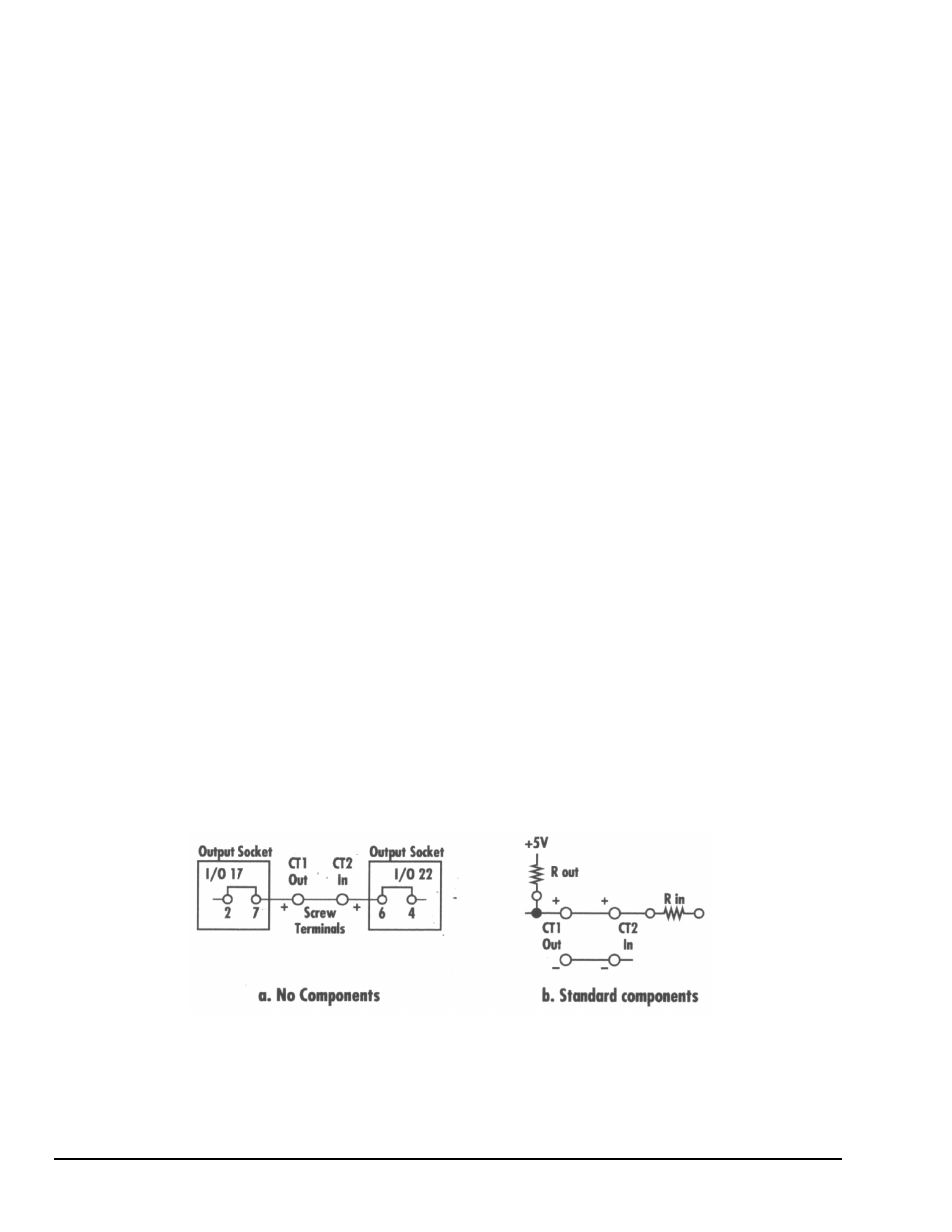
Figure 14-4a shows a pulse counting application with two counter/timers cascaded to count as high as
4,294,967,296. The output of CT1 is connected to the input of CT2 without using any I/O boards.
Set up both counter/timers as described in the previous section “Pulse Counting” above, except enable the
output of CT1. See the next section for additional information.
Figure 14-4. Cascaded Counter/Timers