Digital components, Installing digital modules, Installing pull-up resistors – Measurement Computing DataShuttle User Manual
Page 26
2-8 DataShuttle - Technical Notes
11-13-01
DataShuttle and DynaRes
Digital Components
Installing Digital Modules
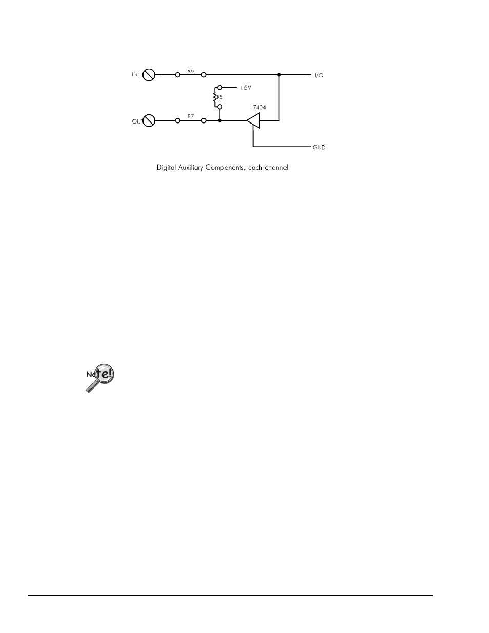
Schematic for Digital Auxiliary Components
Opto22 modules are available to safely connect the digital I/O lines to high voltage AC and DC sources.
There are four basic types:
• AC output: to switch AC power (relay)
• DC output: to switch DC power (relay)
• AC input: to sense AC voltage
• DC input: to sense DC voltage
The output types are used to switch loads on and off. The input types are used to sense the high/low status
of a signal. All of the modules provide optical isolation between the high voltage and terminations.
These modules may be installed on any DataShuttle. First, remove the jumpers labeled R6 and R7. This
disconnects the digital I/Os from the terminals. The module will not fit into the panel until these jumpers are
removed. Then, simply insert the module and fasten the retention screw.
The terminals for that I/O have now changed their function from low voltage I/O to high voltage isolated
I/O. The two terminals become one input channel (high and low lines), or one output channel (like relay
contacts), depending on the type of module you have installed.
When using these terminals as input lines, be sure to connect the positive line to the old
OUT terminal and the negative line to the old IN terminal. Failure to do this will result in
the module not switching.
Installing Pull-up Resistors
As noted in the Applications Reference Manual and previously in this manual, the digital outputs are open
collector and must have a power source connected in order to drive loads. Merely connecting the output
terminal through a load (such as a bulb) and then to digital ground will not work. In this case, a pull-up
resistor connecting the output terminal to a power supply will complete the circuit.
This pull-up resistor is installed in position R8, as shown in the figure on page 2-6, which connects the
output to the unit’s +5 volt power supply. Figures in Chapter 1 show the physical location of R8 on the
DataShuttle. Note that R8 must be installed manually between the +5 volt supply and the output terminal
in question. To install this resistor, push the resistor ends through the holes for R8 (from the terminal side)
until the resistor lies flat with the panel surface. On the backside, solder the wires to the holes. Clip off the
extra wire with pliers. This connection does not require any additional traces to be cut. Use a 4.7K resistor
to give 1mA current flow or a 2.3K resistor to give 2mA current flow.