Piezoelectric sensors, Piezoelectric sensors …… 13-5 – Measurement Computing DataShuttle User Manual
Page 105
DataShuttle and DynaRes
11-12-01
Analog Input & Output 13-5
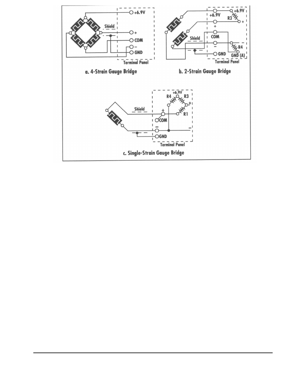
Figure 13-2. Strain Gage Connections
Piezoelectric Sensors
Our data acquisition boards can be used with piezoelectric sensors to monitor vibration, audio and other
mechanical and acoustic effects. Piezoelectric sensors rely on the piezoelectric effect, where a crystal
generates a voltage when it is subjected to stress or strain. Piezoelectric sensors are a good, inexpensive
sensor for the monitoring of acoustic, mechanical and audio disturbances provided an accurate quantitative
reading is not required.
Figure 13-3a shows a simple DC-coupled piezoelectric sensor configuration. In this configuration, the
piezoelectric sensor is connected to the terminal panel, either using a coaxial cable or twisted pair cable.
R3 is the termination resistor, which is used to terminate the piezoelectric sensor signal. In many cases, the
termination resistor is not needed. In some cases, the termination resistor is the characteristic impedance of
the cable, often 50, 75 or 150 ohms. Refer to the technical manual for your piezoelectric sensor for
selection of R3.
Figure 13-3b shows an AC-couple piezoelectric sensor example, which is the most common
implementation. An AC-couple piezoelectric sensor is easier to measure because any DC offset in the
piezoelectric sensor signal is automatically removed for you. The capacitor C and the resistor R3 form a
high-pass filter network, which specifies the lowest frequency signal, which will be transmitted, to your
analog input board. This lowest frequency point is given by:
F= 1
÷ (2πR3C)
Install capacitor C in location R1 or R2. You must select R3 to be large compared to the output impedance
of your piezoelectric sensor, then select C to set the lowest frequency which you wish to digitize via the
data acquisition board. Refer to your piezoelectric sensor manual for details.