Auxiliary analog and digital components, Auxiliary components – Measurement Computing DataShuttle User Manual
Page 61
DataShuttle and DynaRes
11-12-01
Introduction to Terminal Panels 6-5
When two T71s are used with a 16-channel DynaRes, both terminal panels have access to the one
counter/timer on the board. The first T71 will access the counter/timer through the lines shown in the first
column above. The second T71 uses the lines shown in the second column. Both sets of lines cannot be
used at the same time.
Auxiliary Analog and Digital Components
Auxiliary Components
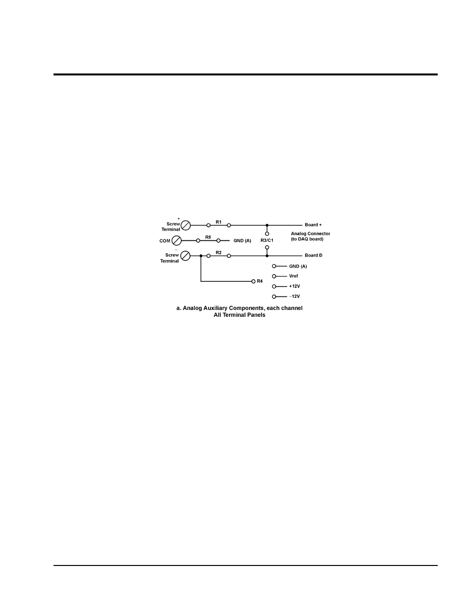
Auxiliary Components are required by some sensors, are used to protect digital signals, or are used to pull
digital outputs to a set level. There are two areas (one digital and one analog) on the terminal panels for
installing auxiliary components; schematics of both are shown in detail in Figures 10(a),(b), and (c) below
and on page 6-8. Note that each channel on the terminal panel has room for its own separate set of auxiliary
components.
When using analog auxiliary components R1, R2, and R5 you must cut the shorting metal trace that
connects the two ends of the line together before installing any of the components in these locations. Use a
sharp knife to carefully slice through the trace without cutting additional traces. In the case of R5 this is a
plastic covered metal wire. Diagrams of the auxiliary component area, hole functions, and connection
possibilities are shown on page 6-8.
Figure 10 Schematic for Analog & Digital Auxiliary Components