Gilbarco interface unit, Cpu board – Gasboy CFN III Quick Reference Guide v3.3 User Manual
Page 54
CFN III Quick Reference
Page 50
MDE-4483 CFN III Quick Reference Guide v3.3 · August 2005
inherently slow to respond or at sites that have a
large number of pumps and are very busy).
12 The pump is a blender. (The Site Controller may
not be able to keep component product tank
inventories for types of blender pumps that are
not specifically supported by Gasboy.) Do not
use this option for Gilbarco and Tokheim
Blenders.
13 The pump is a TCS configured to always
download prices. (This allows TCS pumps to
display the correct price level for a sale, provided
that the pump’s Tokheim firmware supports the
Mode 25 feature.)
14 Pump is a Gasboy PAC.
15 Single -sided pump (used for PCU auto-
configuration).
16 Tokheim Premier model.
17 Requires start button (not required for Tokheim).
18 Beeps without pressing payment on DPT or
CRIND.
19 Grade-select buttons exist.
20 Beeps when offhook without START key being
pressed.
21 Pump has a lift-lever for offhook.
22 Pump is the master of the pump chain. Turning
on this pump activates all other “pumps” in its
cluster except other master pumps in that cluster.
23 Wayne 3 product blender, hoses 1, 3, and 5. For
Wayne products V580 and V590U. Previously
these pumps required using 5 hoses, setting the
price code for hoses 2 & 4 to 99. With this
option, only define 3 hoses and the Wayne driver
maps to the appropriate pump positions
automatically.
Tokheim Pump Programming
Mode 19 - set dispenser function code to 0.
Mode 23 - set address (1-16), number of products,
number of sides, and number of prices.
Mode 25 - set price-change mode equal to 1.
Mode 26 - on the Premier should be set as 2.
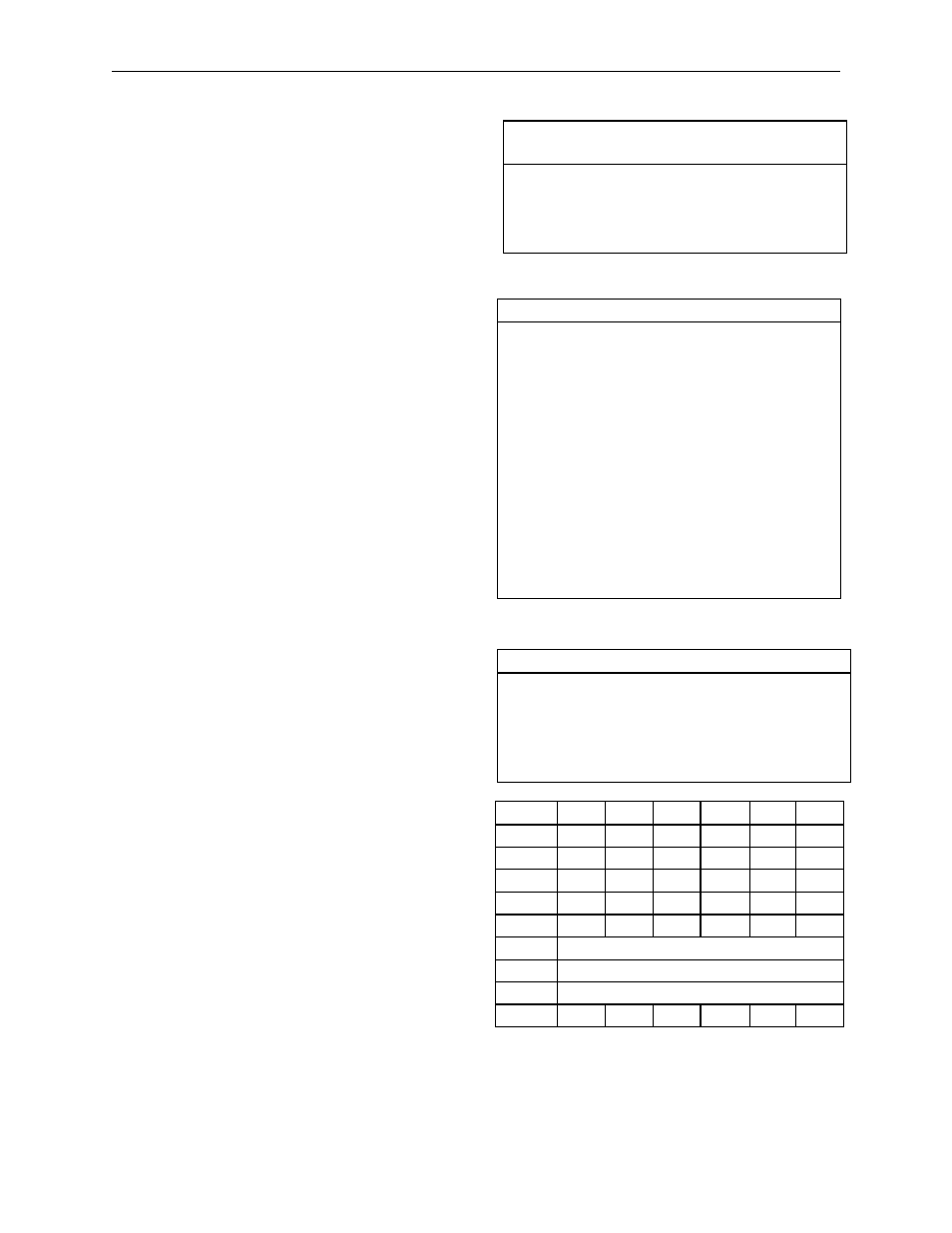
Gilbarco Interface Unit
Part number: C05688. Use a C04500 cable from the
RS422/RS485 junction box to the RS422 port of the
interface unit.
Use Gilbarco firmware version 70.2 or later.
Product authorization does not work with Gilbarco
pumps before version 2.0c of Gasboy’s interface
firmware and version 2.0cp2 of the Site Controller II
software and only with the Advantage Series.
Interface
Terminal
Short
Wire
Color
Terminal Block
Connection
Field
Wire
Color
Gilbarco
dist. Box
Terminal
Legend
Pl-1
red
1+ (top terminal) black box 1
-BLK
Pl-2
black 1- (next down) red
box 1
+RED
P2-1
red
2+ (third down) black box 2
- BLK
P2-2
black 2- (bottom)
red
box 2
+ RED
CPU Board
Jumper
Function and/or Normal Setting
K1
All K1 jumpers are absent.
K2
All K2 jumpers are absent.
K3
Position 1: enables the dead man timer.
K3-1 jumper must be installed.
K3-1 is the pair of K3 terminals closest to
P9, the long double-row offboard connector
at the edge of the board.
Position 2: K3-2 jumper is absent. K3-2 is
the pair of K3 terminals farthest from P9.
K4
----
K5
Battery to U31; must install.
K6
Battery to U32; must install.
K7
Enables the AC power fail circuit; must
install.
K8
K8 jumper is absent.
DIP Switch Bank 2. This switch sets the poll
address and allows memory to be cleared
Position & Definition
Setting(*=customary)
1
debug mode
*closed=normal mode
open=debug mode
2
erase memory on reset
*closed=no
open=yes
3-8
interface address
see below
Address
2-3
2-4
2-5
2-6
2-7
2-8
1
cl
cl
cl
cl
cl
cl
2
cl
cl
cl
cl
cl
op
3
cl
cl
cl
cl
op
cl
4
cl
cl
cl
cl
op
op
5
cl
cl
cl
op
cl
cl
.
.
.
64
op
op
op
op
op
op