Island card reader i, Cpu board, Switches – Gasboy CFN III Quick Reference Guide v3.3 User Manual
Page 41: Jumpers
CFN III Quick Reference
MDE-4483 CFN III Quick Reference Guide v3.3 · August 2005
Page 37
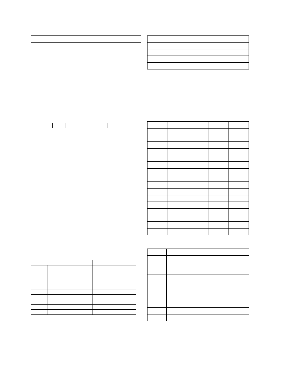
ANSI Setup
FKey Lock
Off
National
Feature Lock
Off
Send
All
Keypad
Numeric
Send Area
Screen
Cursor Keys
Normal
Print Area
Screen
Xfer Term
EOS
Send Term
None
Char Mode
Multinational
Print Term
None
Keys
Typewriter
Print Mode
Auto/Normal
VT 100 ID
VT 100
Auto Answerback
Off
Any commands run at the Site Controller will not be
logged unless you:
• direct output to the logger (use >log with the
command), or
• press
CTRL - SHIFT - PRINT SCREEN
simultaneously. Pressing these keys toggles the
Main port output to the logger. (The message
line at the top of the screen toggles between FDX
MAIN and FDX>AUX.)
All other parameters should be set as shown above.
Island Card
Reader I
CPU Board
Part number: C05375.
Switches
DIP Switch Bank 2
DIP switch 2 on the reader terminal CPU board sets
options, including the reader terminal address:
Position & Definition
Setting(*=customary)
1
see below
*open
2
decimal point
*open=enable
closed=disabled
3
DES PIN encryption
*closed=disabled
open=enabled
4
reader type
see below
5
gate reader
*open=disabled
closed=enabled
6
reader type
see below
7-10
address
see below
Reader Type
2-4
2-6
mag swipe without optical
closed
closed
mag swipe with optical
closed
open
mag insert
open
closed
optical
closed
open
Notes
Position 2-1 is not used in SC II software versions
1.0 and later. (In software versions 0.2 and before, 2-
1 is the deadman timer switch: open
(default)=enabled, closed=disabled.)
Position 2-5—In SC II software versions 0.2 and
before, 2-5 is the CRC switch; open=CRC enabled,
closed= disabled.
Address
2-7
2-8
2-9
2-10
1
cl
cl
cl
cl
2
cl
cl
cl
op
3
cl
cl
op
cl
4
cl
cl
op
op
5
cl
op
cl
cl
6
cl
op
cl
op
7
cl
op
op
cl
8
cl
op
op
op
9
op
cl
cl
cl
10
op
cl
cl
op
11
op
cl
op
cl
12
op
cl
op
op
13
op
op
cl
cl
14
op
op
cl
op
15
op
op
op
cl
16
op
op
op
op
Jumpers
Jumper Function and/or Normal Setting
K1
Position 1=LCD display
Position 1 and 2=Beckman alphanumeric
display
K2, K3
K2 in position 2 and K3 in position 1=Omron
reader
K2 in position 1 and K3 in position
2=Magstripe reader
K4
----
K5
Position 2=2K RAM; position 1=8K RAM
K6
Jumpered when using motorized reader