Figure b-2 and – Comtech EF Data KPA User Manual
Page 89
KPA Ku-Band Indoor Solid-State Power Amplifier
Revision 1
Appendix B
MN/KPA.IOM
B–3
they are not shown in this manual. Contact Comtech EF Data for 1:2 Redundancy Kits and their
pertinent installation diagrams and assembly instructions.
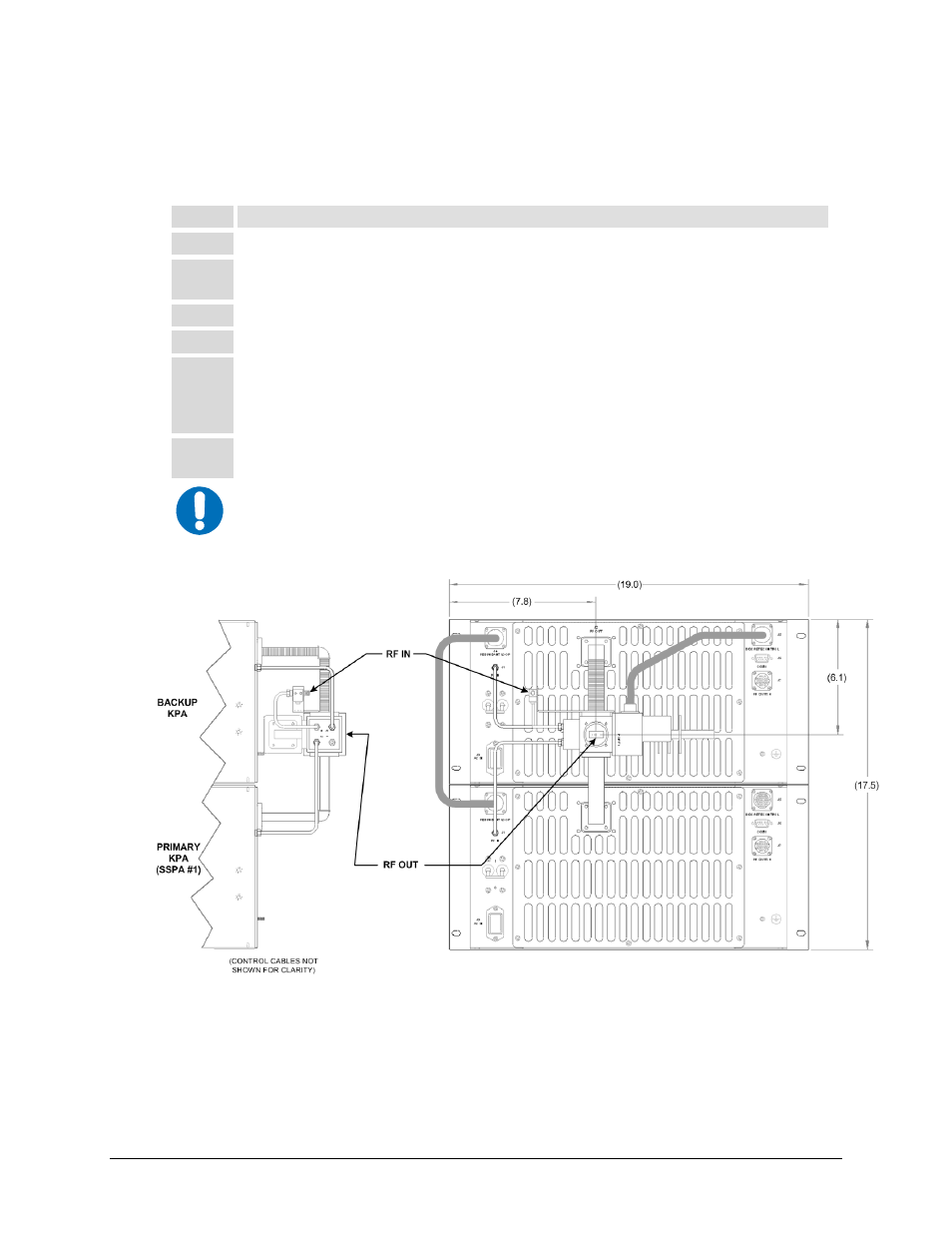
Perform the installation as follows (refer also to Figure B-2 and Figure B-4):
Step
Procedure
1
Assemble the waveguide load and bend to the proper port of the switch.
2
Attach the rigid lower waveguide arm, using the supplied screws. The switch should be installed with
“Port 1” facing outward.
3
The upper Waveguide (flexible arm) along with the isolator bracket should be installed next.
4
Complete the installation by attaching the coaxial cables, coaxial load, and control cables.
5
Note that the installation of the control cables determines which unit will function as the backup KPA.
Due to the nature of the dual WG-coax switch, this will always be the upper unit. Therefore, the end
of the redundant loop cable (40, Figure 2-1) labeled “BU SSPA,” should be connected to J4 of the
upper (backup) unit.
6
The appropriate end of the control cable attaching to the Waveguide Switch (Item 50) should also be
attached to the Backup Unit at the J7 RF SWITCH connector.
IMPORTANT
A gasket must be installed between each waveguide interface. If both waveguide
surfaces are grooved, use a thick gasket. If only one surface is grooved, use a
thin gasket.
Figure B-2. 1:1 Redundancy Installation – Complete