3 utility connections, 1 sample port connectors (front panel), 2 j4 redundant loop connector – Comtech EF Data KPA User Manual
Page 36
KPA Ku-Band Indoor Solid-State Power Amplifier
Revision 1
Connectors and Pinouts
MN/KPA.IOM
3–4
3.3
Utility Connections
3.3.1
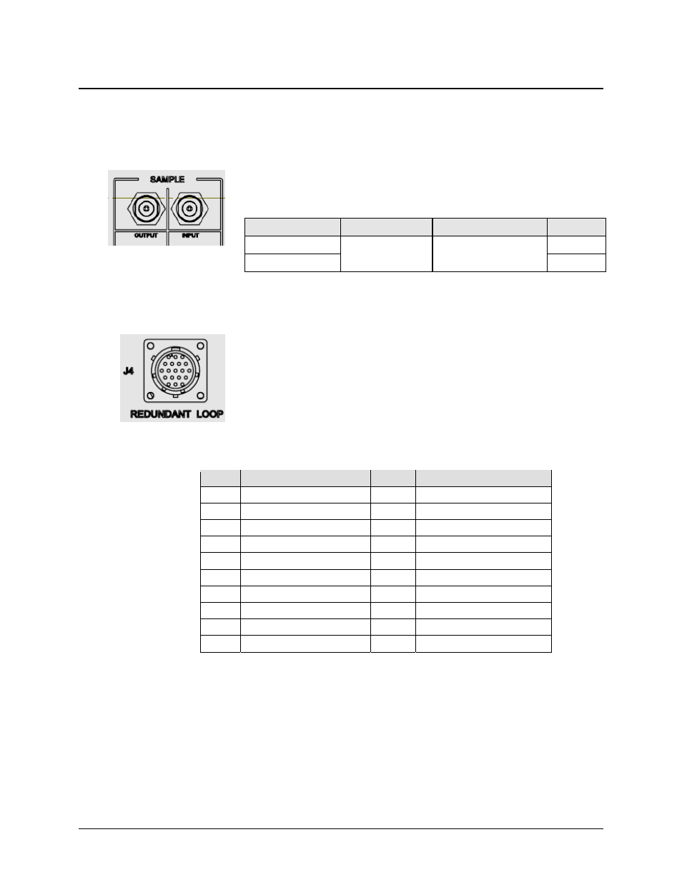
Sample Port Connectors (Front Panel)
The SAMPLE INPUT / OUTPUT ports are Type ‘N’ female connectors,
providing easy user access –20 dBc and –40 dBc test points on the KPA
front panel.
3.3.2
J4 REDUNDANT LOOP Connector
The J4 Redundant Loop connector is a 19-pin circular connector, type
MS3112E14-19S. The pin-out specification is contained in Table 3-2.
This connector is used only in redundant configurations – see Appendix
B. KPA REDUNDANT OPERATIONS for further information about
use of the KPA in 1:1 or 1:2 redundancy.
Mating connector: ITT KPT06J14-19P or MS3116J14-19P
Table 3-2. J4 Redundancy Loop Connector Pinout
Pin #
Description
Pin #
Description
A
Loop In 1
L
SumFlt 2 NO
B
ADDR 2
M
SumFlt 2 Common
C
Loop In 2
N
Local Loop Out
D
Loop Out 2
P
SumFlt 1 NO
E
ADDR Common
R
SumFlt 1 Common
F
ADDR 1
S
Local SumFlt Common
G
Loop Out 1
T
Local SumFlt NO
H
HSB +RX/TX
U
No Connect
J
HSB – RX/TX
V
No Connect
K
Local Loop In
Name
Connector Type
Description
Direction
SAMPLE | OUTPUT
Type ‘N’ Female
–20 dBc / –40 dBc
Sample Test Port
Input
SAMPLE | INPUT
Output