B.2 redundancy operation, B.3 redundancy kit installation – Comtech EF Data KPA User Manual
Page 88
KPA Ku-Band Indoor Solid-State Power Amplifier
Revision 1
Appendix B
MN/KPA.IOM
B–2
B.2
Redundancy Operation
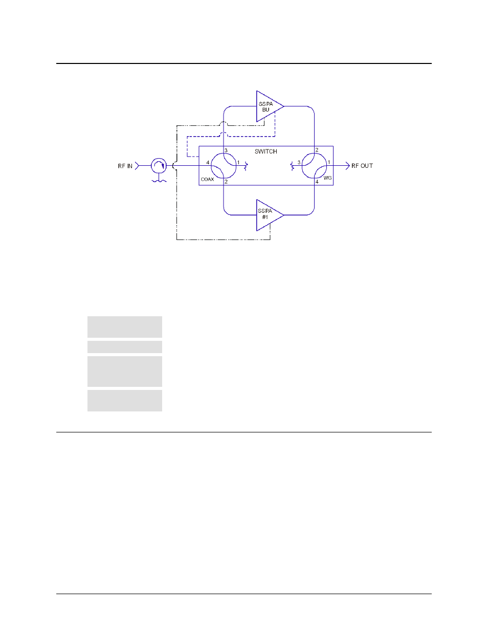
Figure B-1. 1:1 Redundancy Block Diagram
Figure B-1 shows the block diagram for a typical 1:1 redundant system. Whether 1:1 or 1:2
redundant operations are employed, note the following:
Normal Operation
Incoming RF signals are routed through the primary online SSPA (1:1), or SSPA (1:2) to
the system output(s) by the combination waveguide/coax switch(es).
Controller Mode
With the backup SSPA in the controller mode, it monitors the Online Unit(s) for faults.
Fault
When a fault occurs in an Online Unit, the backup SSPA automatically configures itself
with the settings of the faulted Online Unit. (These now active settings also incorporated
any user defined offsets that may have been programmed into the Backup Unit.)
Waveguide
The position of the waveguide/coax switch also is automatically changes to route the
signal through the Backup Unit, thereby minimizing the loss of traffic.
B.3
Redundancy Kit Installation
Comtech EF Data KPAs are easily configured for optional redundant operation by using an optional
Redundancy Kits. These kits include all the necessary control, semi-rigid, and waveguide cabling,
and the appropriate waveguide/coax switches and terminations. Figure B-2 and Figure B-4 show a
typical 1:1 redundant system assembly; the associated parts lists are provided in Table B-1.
As shown, the primary and backup KPAs are typically installed adjacent to one another in a
standard 19-inch wide (48 cm) equipment rack. Because of the configuration of the dual Waveguide
Coax Switch, the upper KPA always acts as the “Backup” unit.
Note: Redundancy kits are available for 1:2 configurations, and provide all required cabling and
switches. As 1:2 Redundancy Kits are typically designed to a customer’s unique specifications,