1 startup checklist, 2 led indicators – Comtech EF Data KPA User Manual
Page 46
KPA Ku-Band Indoor Solid-State Power Amplifier
Revision 1
Front Panel Operation
MN/KPA.IOM
5–2
5.1.1
Startup Checklist
The user should always perform the following checklist before operating the KPA:
Step
Procedure
1
Check to ensure that the installation is complete.
2
Verify that the KPA is connected to the proper Prime Power Source, RF input, and
RF output.
3
Switch on the Prime Power Switch (located on the rear panel).
4
Once the Prime Power Switch has been switched on, verify that the cooling fans are
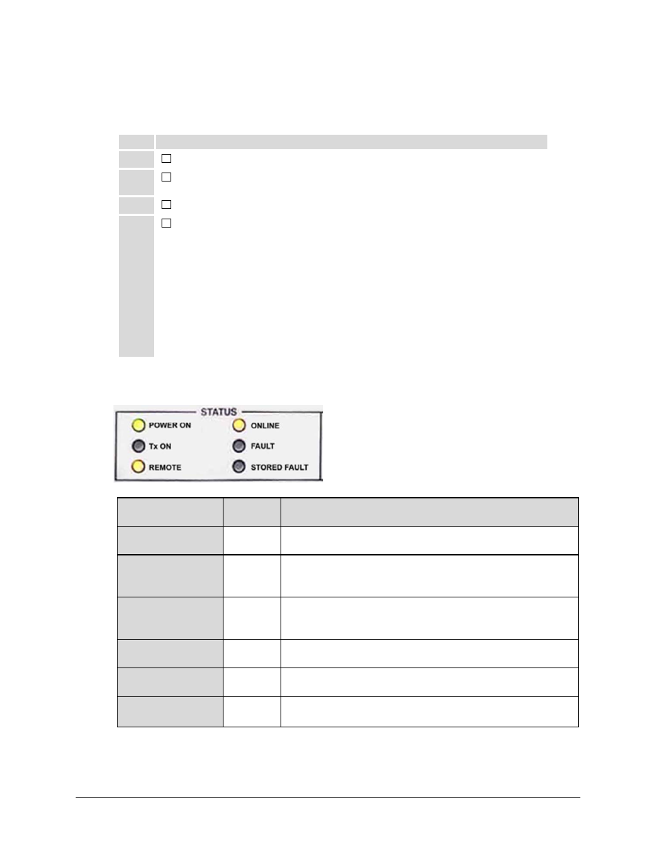
operating and that the six STATUS LED indicators appear as follows:
•
POWER ON
– ON (yellow)
•
Tx ON
– OFF
•
REMOTE
– ON (yellow)
•
ONLINE
– ON (yellow)
•
FAULT
– OFF
•
STORED FAULT
– OFF
5.1.2
LED Indicators
The operational behaviors of the six front panel
LED indicators is as follows:
LED
Color
Condition (When Lit)
POWER ON
Green
Indicates that power is applied to the unit.
Tx ON
Yellow
Indicates that the transmit function of the unit is on. This
LED indicator reflects the actual condition of the transmit
function.
REMOTE Yellow
Indicates that the unit is operating in remote control mode,
where commands and data are transferred via an EIA-485
(EIA-232 is optional) serial communications link.
ONLINE Yellow
Indicates that the unit is operating online to transmit data.
FAULT Red
Indicates that a fault condition exists.
STORED FAULT
Red
Indicates that the fault has been logged and stored. The
fault may or may not be active.